SG_FSE_SiplaceHF_HF3_00193901-05_eng.pdf - 第189页
1 - 23 S tudent Guide SIPLACE HF/HF3 Edition 09/2005 5 Gantry 23 5.5 Axis control 5.5.1 Part s for the axis control The control loop for control th e X- and Y -axis in general consist of the following p arts: – Axis boar…
1 - 22
Student Guide SIPLACE HF/HF3
5 Gantry Edition 09/2005
22
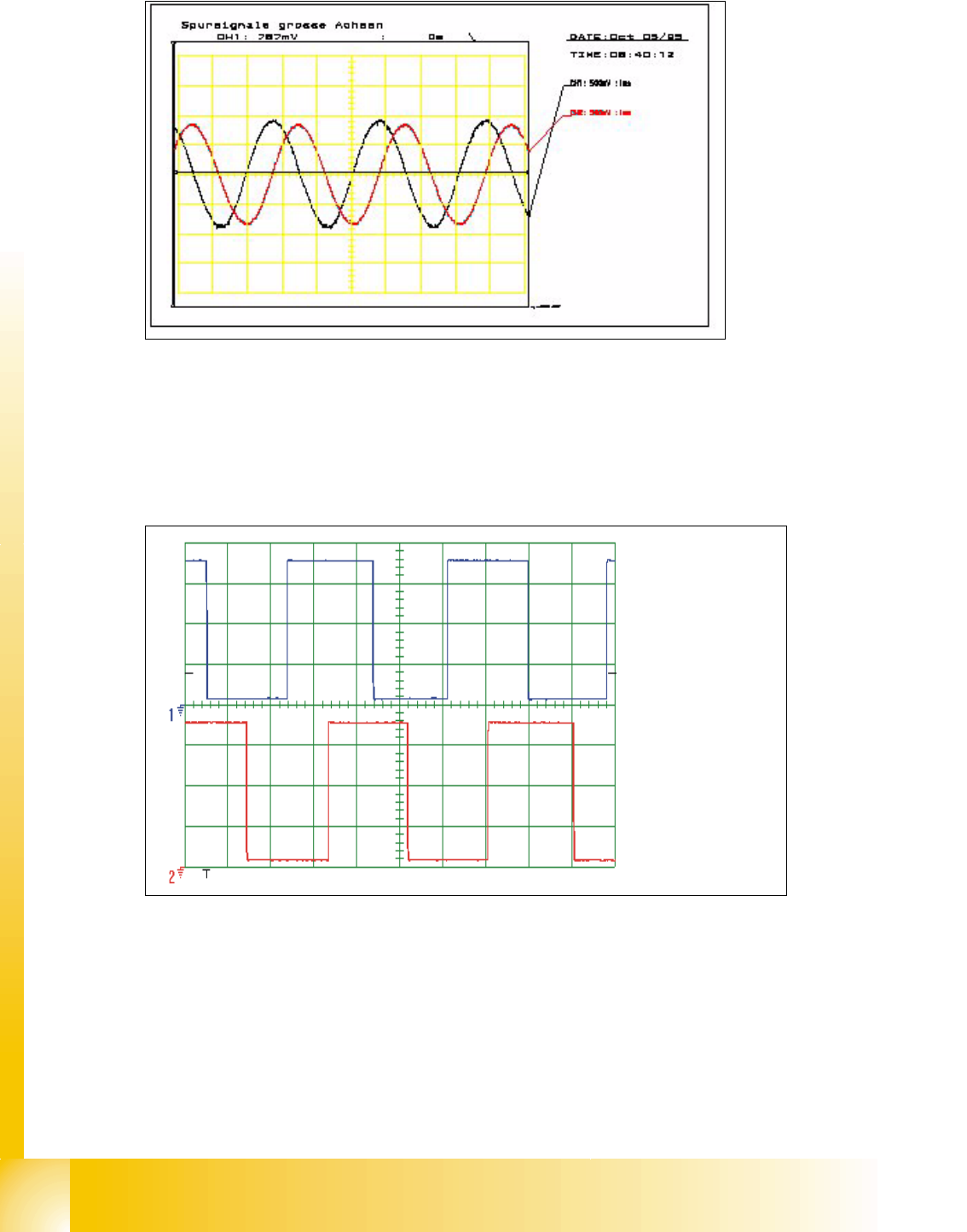
Fig. 5.4 - 7 Analog track signals 90° phase shift
5.4.2.2 Digital Track signals
To check the track signals use the same test setup which is descriped under point 5.4.1.2 .
The measurement procedure is the same as descriped under point 5.4.2.1 .
Fig. 5.4 - 8 Digitale track signals 90° phase shift
Spur A / track A
Spur B / track B
1 - 23
Student Guide SIPLACE HF/HF3
Edition 09/2005 5 Gantry
23
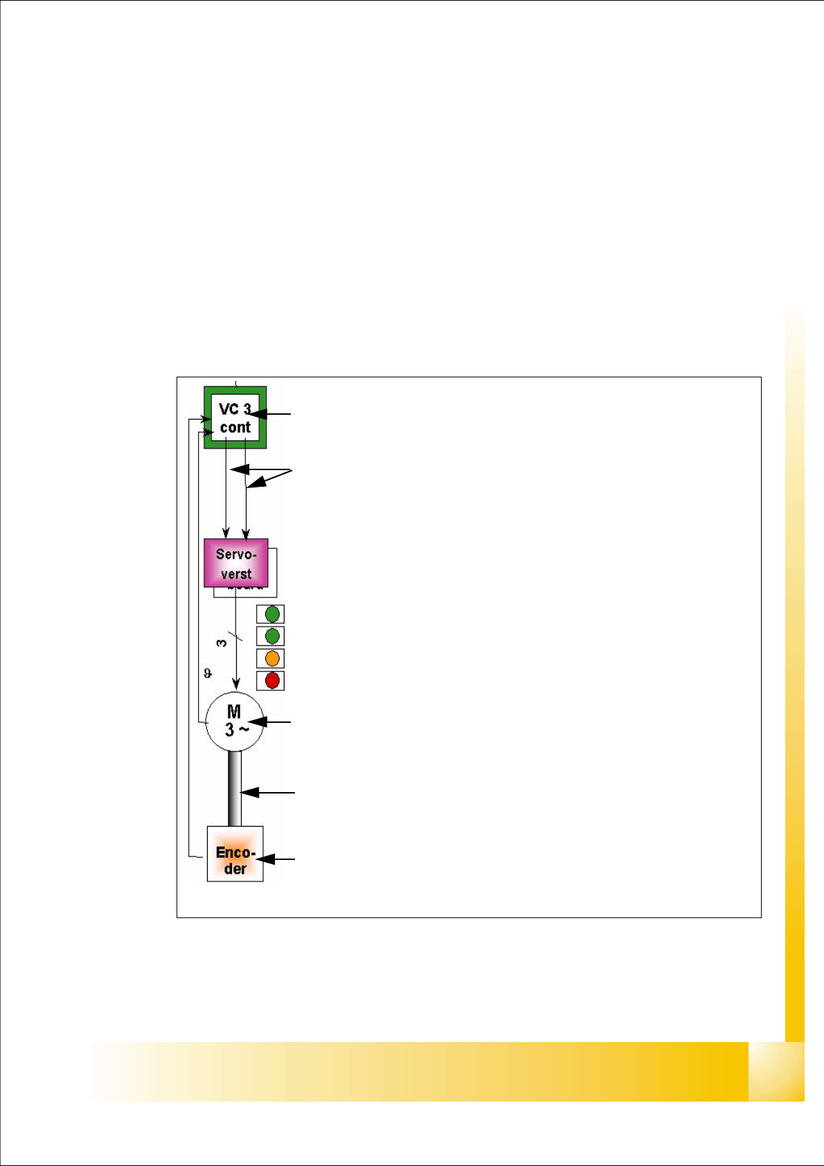
5.5 Axis control
5.5.1 Parts for the axis control
The control loop for control the X- and Y-axis in general consist of the following parts:
– Axis board with VC 3 Controller
– Servo board (TDS)
– 3 Phase AC linear motor
– Measurement system (Incremental scale and encoder)
All linear motors have temperature sensor to protect it against high temperature.
Fig. 5.5 - 1 Parts "Axis control"
Axis board A363 with VC 3 Controller (VC = Velocity Commutation)
Control signals I
soll "W" and I soll "U"
Servo board control directly the linear motor, Intermediate (DC) voltage cir-
cuit is 250V.
LED‘s on Servo board:
– Power supply ON
– Servo enable, it the enable signal from the axis board.
–Display I
RMS limit shorter than 2,5 s.
– Error: Over voltage, -current, -temperature longer than 2,5 sec.
3 Phase AC linear motor X-and Y-axis with integreted temperatur sensor.
Between motor and incremental encoder exist a fixed mechanically connec-
tion.
Incremental encoder: Transmitted the correct position to the axis board and
is the only feedback signal to control the motor (Track signals).
1 - 24
Student Guide SIPLACE HF/HF3
5 Gantry Edition 09/2005
24
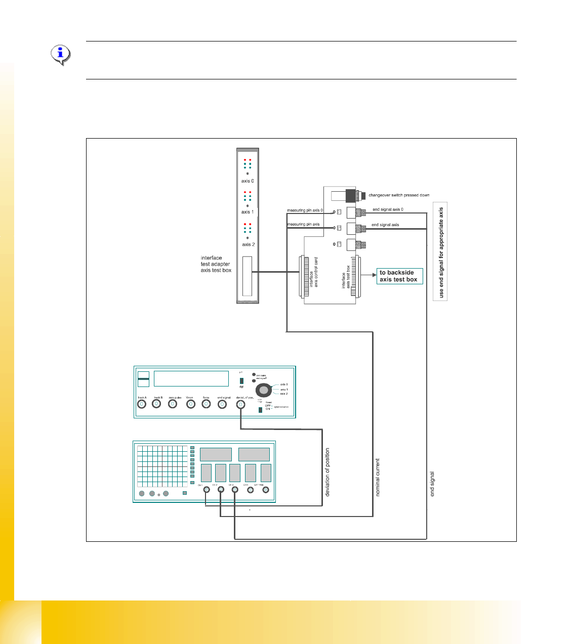
5.5.2 Check dynamic X-axis
The inspection of dynamics occurs with the following signals:
– Deviation of position
– Nominal current
– End signal ( Adapter board Axis in target position)
– Actual position = nominal position ( Axis testbox Output end signal)
Please Note:
To check the axis dynamic, please use the "Adjustment manua HF platform".
5.5.2.1 Test setup with Axis testbox
Fig. 5.5 - 2 Test setup to check the dynamic ,Gantry
– An additional connector on channel 4 is the actual pos.=nom.pos. signal from the axis testbox.
11