SG_FSE_SiplaceHF_HF3_00193901-05_eng.pdf - 第337页
1 - 25 S tudent Guide SIPLACE HF/HF3 Edition 09/2005 7 TWIN-Head 25 7.4.1.6 Vision control board "IC camera" The vision control board is installed in secto r 2 for the T win head on gantry 3 and at sector 4 for…
1 - 24
Student Guide SIPLACE HF/HF3
7 TWIN-Head Edition 09/2005
24
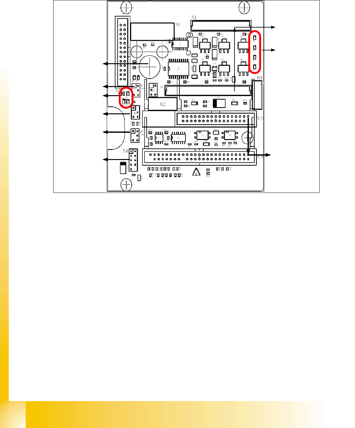
7.4.1.5 TWIN-Head main board
The main board is mounted directly on the top of the frame of the TWIN-head. This board is con-
nected to the head adapter via ribbon cable (one ribbon cable for each axis).
Fig. 7.4 - 5 Main board at TWIN-head segment
1. Connector for the 16 Bit CAN Bus Processor (Control the analog or digital vacuumgenerator)
2. LED´S (Description from top to bottom)
- D6 BERO Z-axis top (not used)
- D1 not defined
- D2 Clamping Z-axis (yellow) LED off, retract unit is at top position.
- D15 Temperature monitoring Z-axis linear motor (red) LED on, is ok.
3. Connectors to the head adapter
4. Connector track signals Z-axis
5. Connector BERO Z-axis (not used)
6. Connector pneumatic valve (retract unit)
7. LED‘s: D7- is ON after reference run
D8- protect Z-axis without function
D9 - without function
D10 - green LED ON 24Vfor the vacuumgenerator
D14 - Alarm output for the vacuumgenerator ( red LED ON vacuumgenerator defect)
8. Connector for valve (only 24 Volts on pin 2 and 4 measured)
9. Hole for pneumatic pipe to the vacuum generator
1
2
3
4
6
5
7
8
9
1 - 25
Student Guide SIPLACE HF/HF3
Edition 09/2005 7 TWIN-Head
25
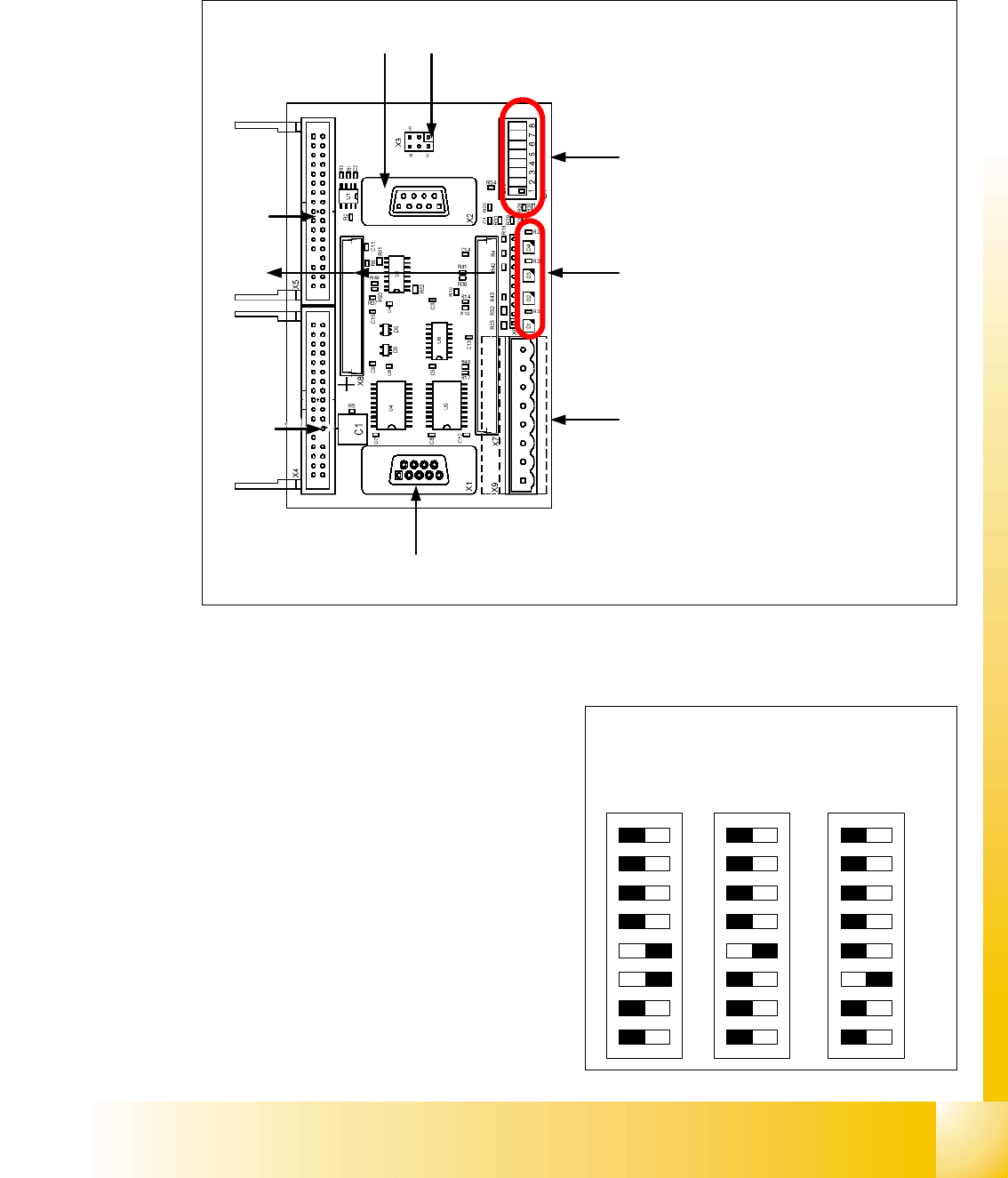
7.4.1.6 Vision control board "IC camera"
The vision control board is installed in sector 2 for the Twin head on gantry 3 and at sector 4 for
the Twin head on gantry 1 (only for HF).
Fig. 7.4 - 6 Vision control board IC camera
1. Connector for FC Camera illumination
2. Connector for IC Camera illumination
3. Service connector
4. LED‘s (downwards D4 - D1)
– + 5 V / -15 V / +15 V / +40 V
5. DIP Switch
6. Connector CAN Bus
7. Power supply Vision control board
Connector for DC/DC converter (Section2)
for DC/DC distributor (section 4)
8. Connectors for CAN Bus Processor 16 Bit
9. Flash signal
1
6
3
4
5
2
7
8
9
to 5)DIP-Switch
(1) CAN- Terminator
(2) RESET
(3) Bootstrap
(4) TEST
(5) P1 Address -Switch
(6) P0 Address -Switch
(7) CAN - ID 1
(8) CAN -ID 0
ON
78123456
ON
78123456
ON
78123456
Gantry 1
for HF
Gantry 3
for HF/HF3
Gantry 2 for
HF (504)
1 - 26
Student Guide SIPLACE HF/HF3
7 TWIN-Head Edition 09/2005
26
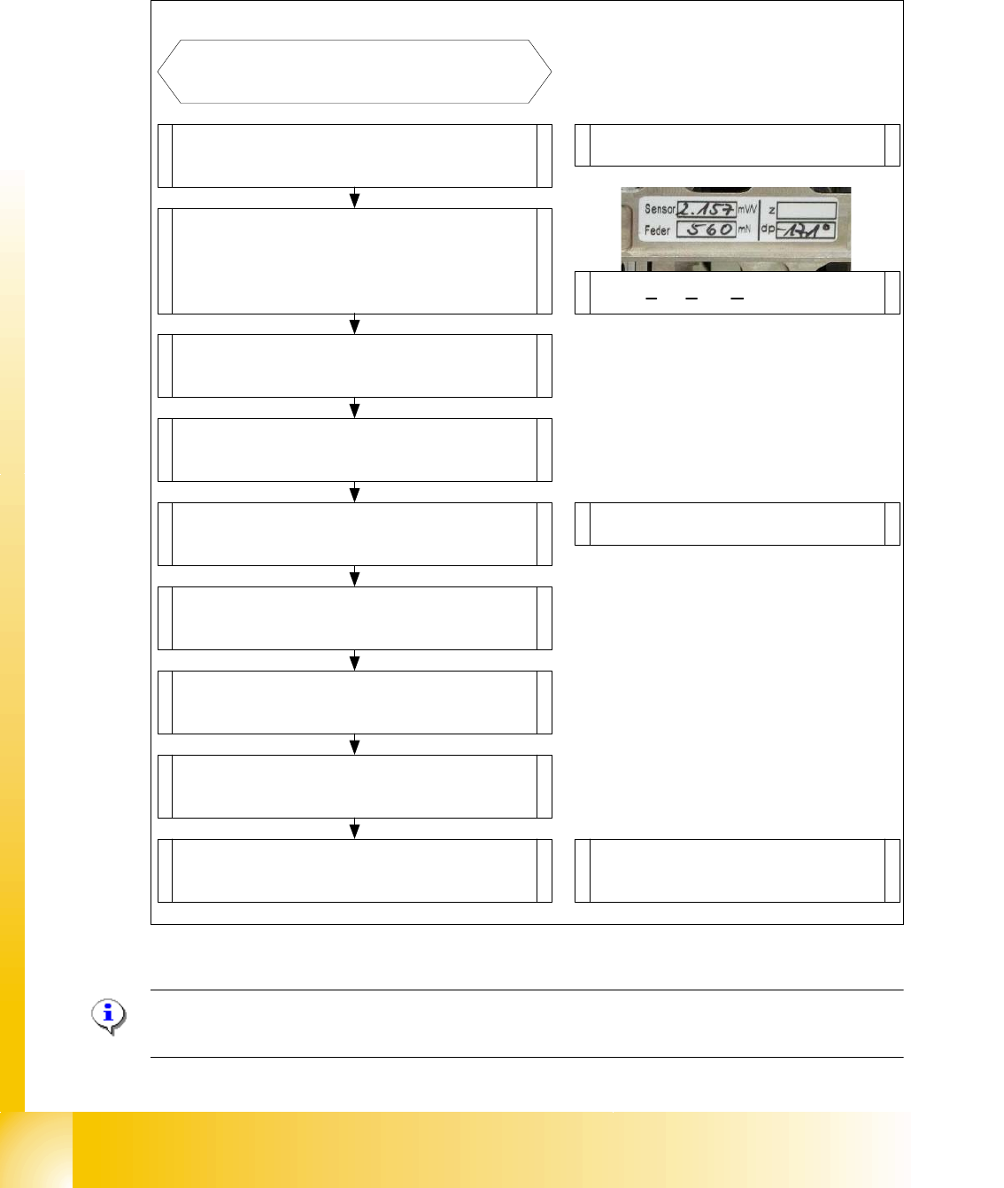
7.4.2 Parameter and Calibrations
7.4.2.1 Overview calibration steps and parameter in the Sitest
Fig. 7.4 - 7 Overview calibration steps and parameter
Please Note: This steps are necessary during the first initial setup or a replacement of the TWIN
Head modul. The detail description are explained on the following pages.
Type in the parameters for the strain
gages(Force sensor), spring pre-tension,
and the standard values for the Z-axis
(max.-,min.- travel range and ZPC*) and
ZPC* D-axis .
Switch ON the machine and start
the Sitest
Note: Don`t start the reference run
Start the reference run D-axis
Calibrate D-axis
Start the reference run Z-axis
Determined the zero point correction in
the Menu "Calibration functions"
Precondition for further calibration:
Entire reference run
Precondition:Twin head Modul is
mounted and electrical and pneumatic
connections are fixed.
Compensation the vacuum control
system in the Menu "Head board"-->
"Zero calibration for pressure regulator"
Calibrate closed vacuum in the Menu
"Twin head-->Calibration functions"
Check the air kiss and the pressure
tightness of the vacuum system in the
Menu "Twin head-->Head board"
Calibrate Twin head and nozzle changer
in the Main menu
"Sitest --> All Heads and Cameras"
Note: The first garages have to be
empty at the nozzle changer and the
the fill level must be correct.
Check the zero calibration of the vacuum
control system in the Menu "Head board"
* ZPC: Zero Point Correction.