SG_FSE_SiplaceHF_HF3_00193901-05_eng.pdf - 第332页
1 - 20 S tudent Guide SIPLACE HF/HF3 7 TWIN-Head Edition 09/2005 20 Description LED‘S and DIP switch head interface: 7 LED 1-7 (functional check) – SPI - Serial parallel in terface (A/D or D/A converter in future) – D-ON…
1 - 19
Student Guide SIPLACE HF/HF3
Edition 09/2005 7 TWIN-Head
19
7.4 Adjustments
7.4.1 Description of the switches and boards on the TWIN-Head
7.4.1.1 Head interface
The same head interface board is used on Gantry 1/4 and Gantry (2)3 for the TWIN-head and
C&P head.
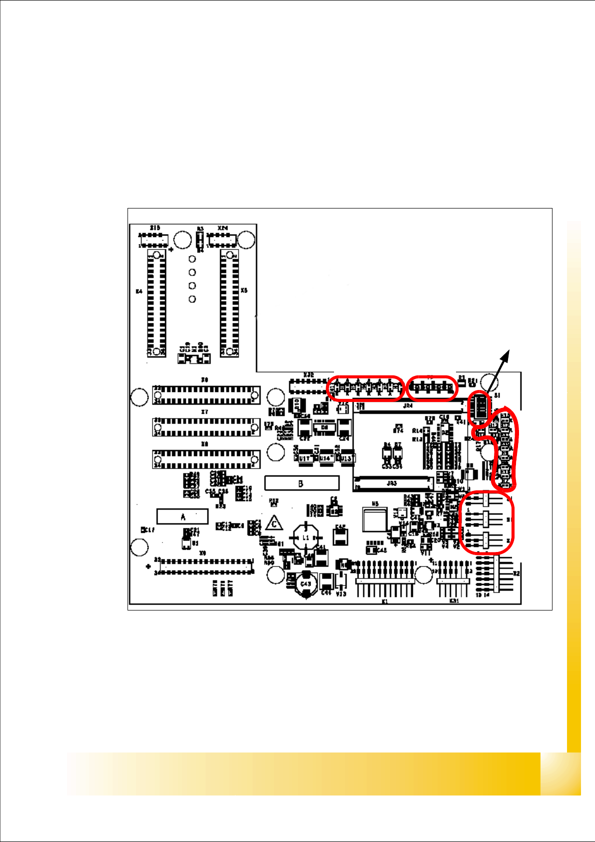
Fig. 7.4 - 1 Head Interface
1. X11 Connector Temperature sensor X-Axismotor
2. X17 Connector BERO Travel range X-Axis
3. X16 Connector BERO Travel range X-Axis
4. X15 Connector for incremental encoder X-Axis
5. X24 Test connector digital track signals X-Axis
LED 1-7 TP 1-8
LED 1-10
DIP Switch
1
2
3
4
5

1 - 20
Student Guide SIPLACE HF/HF3
7 TWIN-Head Edition 09/2005
20
Description LED‘S and DIP switch head interface: 7
LED 1-7 (functional check)
– SPI - Serial parallel interface (A/D or D/A converter in future)
– D-ON - Digital ON 5V DC/DC Converter
– H-OK - Head adapter board connected
– C-In - CAN Internal not used
– MRST - Main Reset
– F-UC- not used
– MP - Main Power fail, indicates 5 V power supply being missing at the machine (e.g. CAN
Bus)
LED 1-10 (LED´s for voltages)
– Vcc - Power supply +5 V head interface
– N15V - Minus 15 Volt (from the Axis unit--> Error--> LED red)
– P3,3V - not used
– P15V - Plus 15 Volt (from the Axis unit--> Error--> LED red)
– P24V - 24 Volt power supply (e.g.stepper motor)
– AV ER - not used
– EN AN - not used
– P5V - 5 Volt Power supply track signals X-Axis --> ON Power fail
– VccF - 5 Volt for digital
– TMP - Temperature monitoring X-Axis
Please Note:
The DIP Switch configuration for the gantry configuration is decribed in chapter gantry.
1 - 21
Student Guide SIPLACE HF/HF3
Edition 09/2005 7 TWIN-Head
21
7.4.1.2 Vision board
The vision board is connect on the top of the head interface. That board is also used on the
gantry 1 with a C&P head.
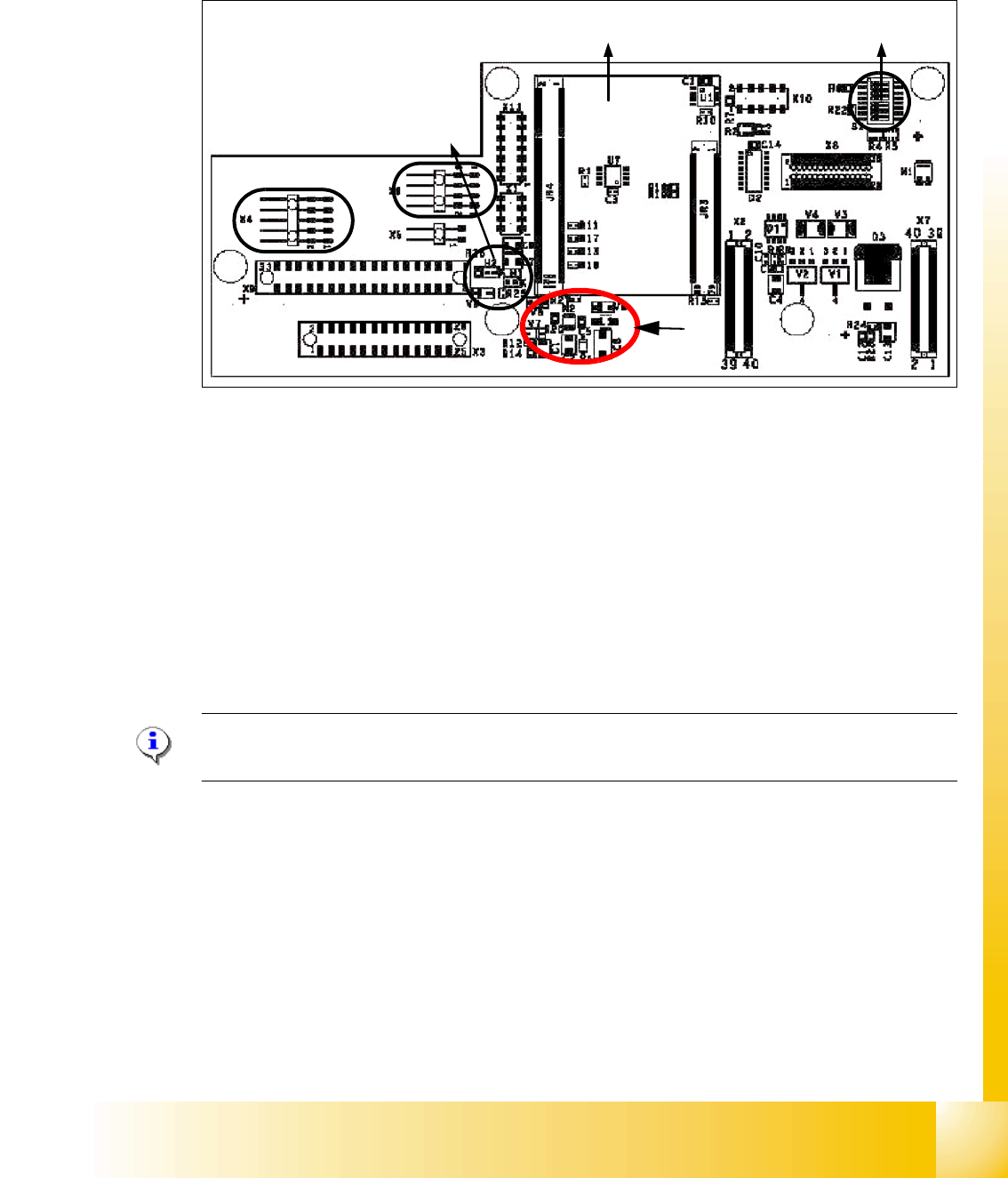
Fig. 7.4 - 2 Vision board
1. Connector illumination PCB camera
2. Connector video signals PCB camera
3. LED‘s P15V - 15Volt / Vcc - Power supply Vision board
4. DIP Switch
5. CAN Processor 16 Bit (additional board on the Visionboard)
6. DC/DC Converter 15 --> 5V for Visionsystem
Please Note:
The DIP Switch configuration for the gantry configuration is decribed in chapter gantry .
4
5
1
3
2
6