SG_FSE_SiplaceHF_HF3_00193901-05_eng.pdf - 第397页
1 - 1 1 S tudent Guide SIPLACE HF/HF3 Edition 09/2005 9 Modular conveyor 11 9.2 Adjustment s on the modular conveyor Please Note: When any settings are mad e on the lifting table, th e liftin g table must be secured to p…
1 - 10
Student Guide SIPLACE HF/HF3
9 Modular conveyor Edition 09/2005
10
9.1.12 Technical data - dual conveyor
9
9.1.13 Technical data - flexible dual conveyor
Fixed conveyor side Right (standard), left (optional)
Max. component height 6 mm for the 12-segment Collect&Place head
8.5 mm for the 6-segment Collect&Place head
PCB format(LxW) 50 mm x 50 mm to 450 mm x 250 mm
2" x 2" to 18" x 8,5"
long board: length up to 610 mm (24"), (option)
PCB thickness 0.5 mm to 4.5 mm
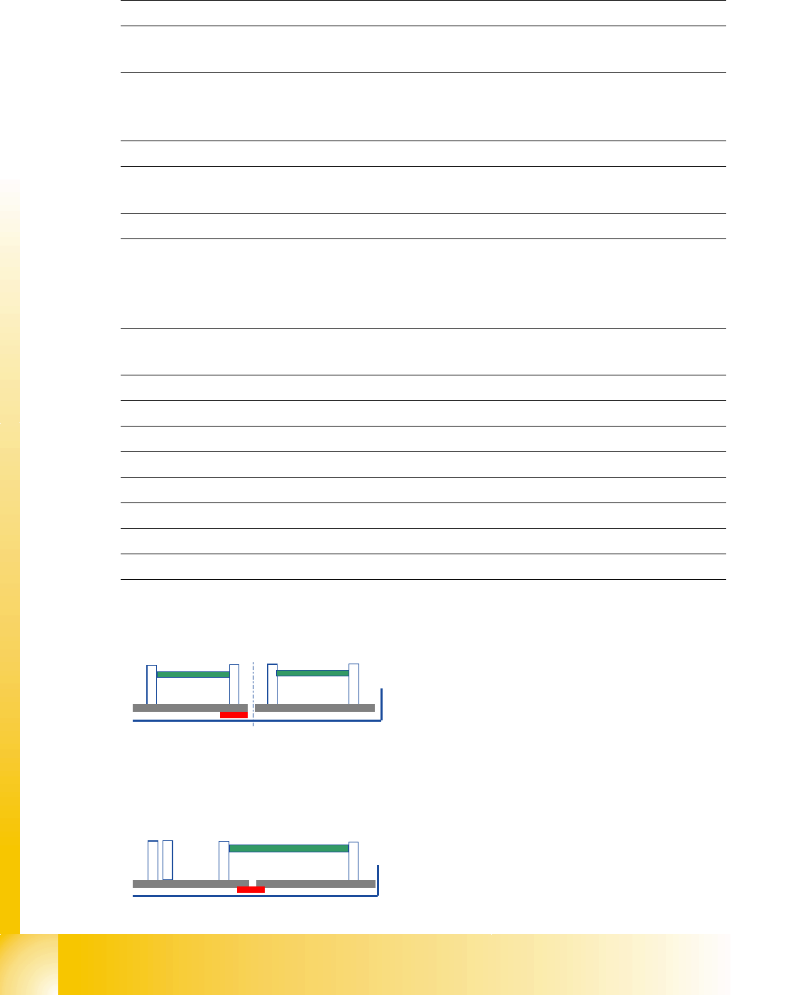
Max. PCB warpage upwards: 4.5 mm - PCB thickness
downwards: 0.3 mm + PCB thickness
Clearance on PCB underside max. 40 mm
PCB transport height 830mm ± 15mm (standard)
900mm ± 15mm (option)
930mm ± 15mm (option)
950mm ± 15mm (SMEMA: optional)
Type of interface SMEMA (standard)
SIEMENS (option)
PCB weight 3 kg
Component-free PCB handling edge 3mm
PCB changeover time 2.5 s
Conveyor mode synchronous or asynchronous
Components on each conveyor same or different
PCB width on each conveyor same or different
Ink spot recognition synchronous: not possible, asynchronous: possible
Automatic width adjustment possible
Dual conveyor mode:
max.PCB size 250 x 450 mm (WxL)
In combination with X3/X2/X4 machine only 216x
450mm possible.
Option: Long board option (610 mm) possible
Single conveyor mode:
max.PCB size 450 x 450 mm (WxL)
In combination with X3/X2/X4 machine the conveyor
width up to 380mm possible.
Option: Long board option (610 mm) possible
1 - 11
Student Guide SIPLACE HF/HF3
Edition 09/2005 9 Modular conveyor
11
9.2 Adjustments on the modular conveyor
Please Note:
When any settings are made on the lifting table, the lifting table must be secured to prevent it mov-
ing. Press the emergency stop button.
9.2.1 Belt tension adjustment
Please Note:
The belt tension must be measured at the center of the belt (strand center), i.e. in the middle
where the distance between two idler pulleys is largest.
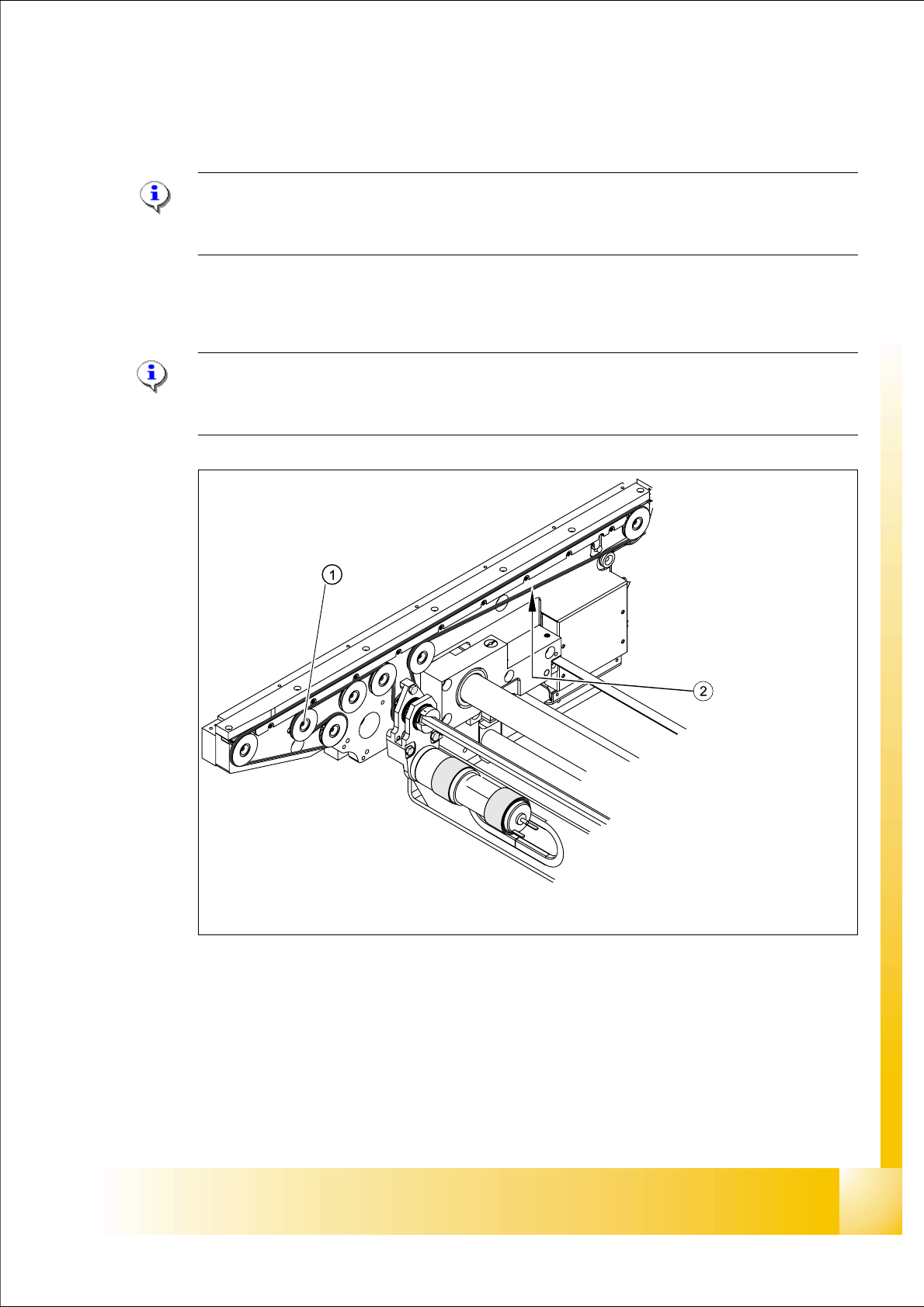
Fig. 9.2 - 1 Measuring and setting the conveyor belt tension
Every conveyor section contains an idler pulley that can be moved.
Loosen the fixing screw
(1) and move this idler pulley in order to set the belt tension for the asso-
ciated conveyor belt
(2).
The belt tension is measured
at the longest point between
two idler pulleys.
Idler pulley: the belt tension is
set by moving the idler pulley.
1 - 12
Student Guide SIPLACE HF/HF3
9 Modular conveyor Edition 09/2005
12
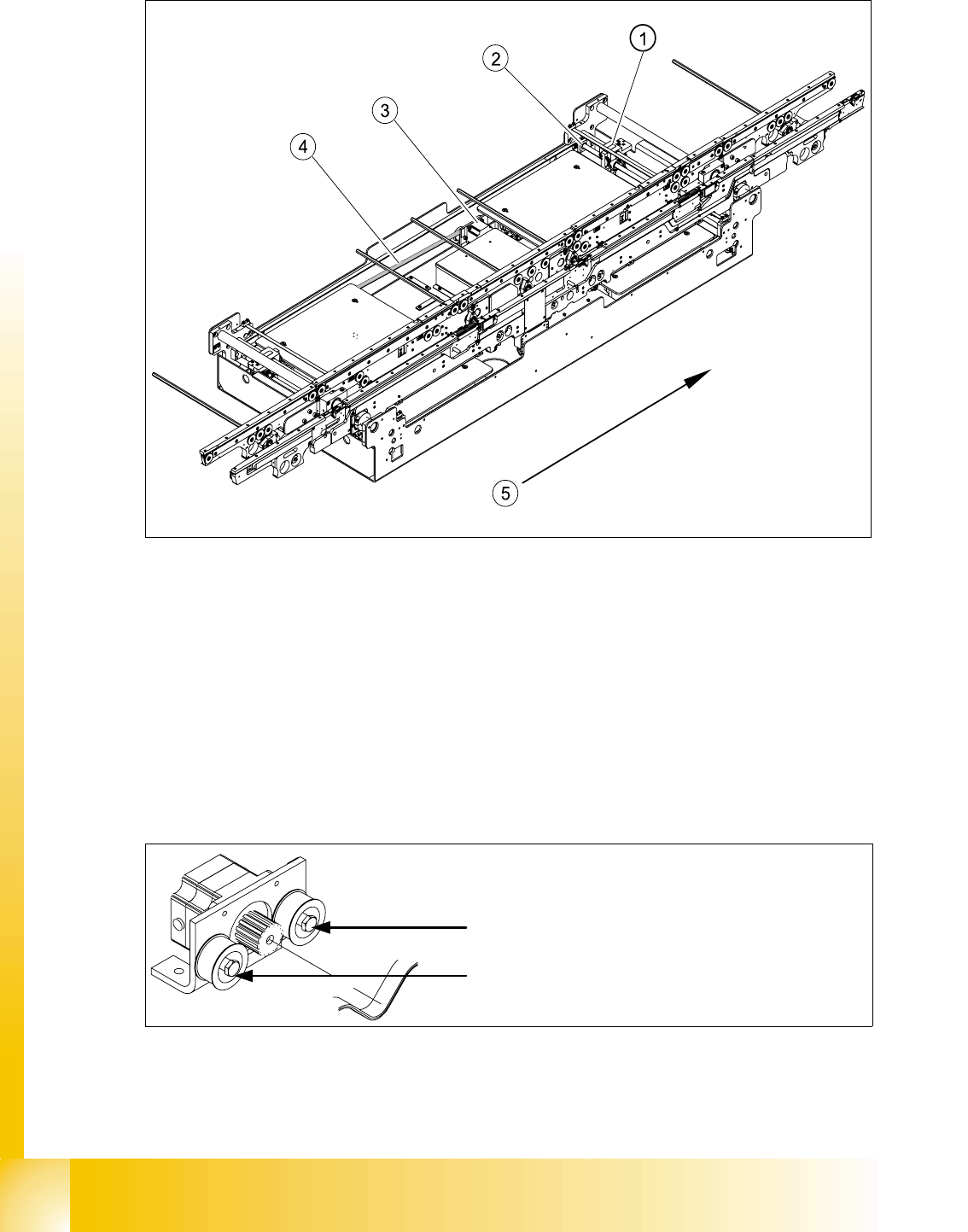
Fig. 9.2 - 2 Measuring and setting the belt tension for the width adjustment (showing HS-60)
Legend
The belt is tensioned by means of cams on the idler pulleys. The idler pulleys are located on the
left and right of the motor.
Fig. 9.2 - 3 Width adjustment motor
(1) Driver (2) Spindle with toothed wheel
(3) Width adjustment stepping motor (4) Toothed drive belt for adjusting the width /
measuring the belt tension
(5) Direction of PCB transport
Loosen the cam shaft on the idler pulley
and set the belt tension.