SG_FSE_SiplaceHF_HF3_00193901-05_eng.pdf - 第61页
1 - 35 S tudent Guide SIPLACE HF/HF3 Edition 09/2005 2 Overview 35 2.2.15.1 Step s when picking up and placing compo nent s – A PCB moves into the placement area of the PCB conveyor . – After the fiducial measurement the…
1 - 34
Student Guide SIPLACE HF/HF3
2 Overview Edition 09/2005
34
2.2.15 DLM2 C&P Head 12/6 segments
The HF machine automatic placement system has depend of the configuration one or two 12-or
6-segment type DLM2 C&P heads.
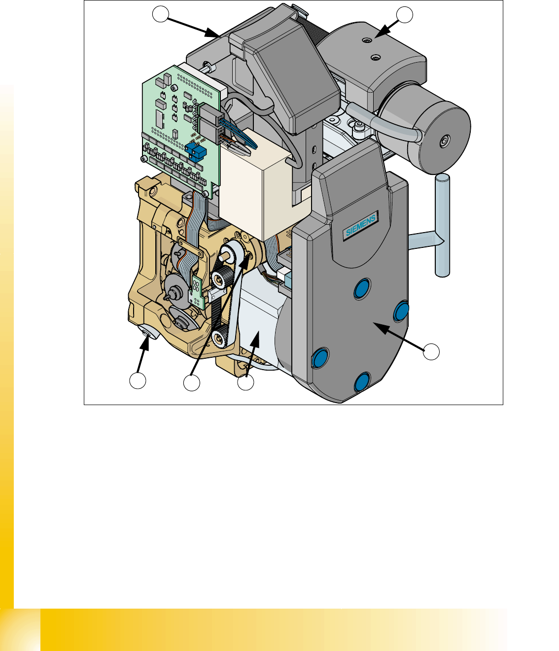
Fig. 2.2 - 23 12-segment DLM 2 C&P head
(1) SP6_12 intermediate distribution board, digital
(2) Star motor
(3) Z-axis motor
(4) step motor
(5) 24x24 component camera (Item no. 00320549-xx)
(6) Vacuum system
Option: DCA camera 15,6 x 15,7mm (Item no. 00337450-01)
Component - sensor (Item no. 00118021-xx)
4
5
3
2
1
6

1 - 35
Student Guide SIPLACE HF/HF3
Edition 09/2005 2 Overview
35
2.2.15.1 Steps when picking up and placing components
– A PCB moves into the placement area of the PCB conveyor.
– After the fiducial measurement the C&P head picks up components from the feeder moduls.
– The components are measured below the component camera and turned in the Dp station into
the correct placement angle position.
– In the star station 1 the component will be placed.
2.2.15.2 Position and function of the individual star stations (see Fig. 2.2 - 24)
Star station 1 2
Pick-up cycle
The nozzle is lowered onto the component. Once the valve positioning unit has opened the vac-
uum circuit to the nozzle, the nozzle sucks the component and removes it from the feeder module.
Placement cycle
The valve positioning unit closes the vacuum channel to the nozzle. The nozzle, together with the
component, is lowered onto the PCB that has been moved into place. A short burst of compressed
air detaches the component from the nozzle and places it on the PCB.
Reject cycle
The valve positioning unit closes the vacuum channel to the nozzle. Defective components are
detached and discarded from the nozzle with a short burst of compressed air.
Star station 3 (only use for the HS60 and S27 HM machine) 2
Note:
The HF machine don‘t use the stepper motor in the reject position, because the reject position now
is the same as the pick up and placment position.
Star station 7 2
The component is optically centered.
Star station 9 2
Pick-up cycle
The nozzle is rotated to the pick-up position.
Placement cycle
The component is turned to the correct placement angle.
1 - 36
Student Guide SIPLACE HF/HF3
2 Overview Edition 09/2005
36
Between star station 11 and 12 2
Check the present and / or height from the component on the nozzle.
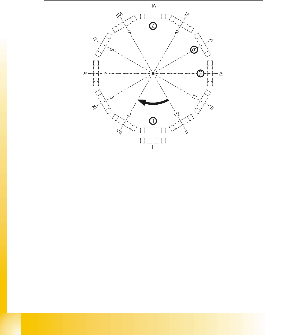
2.2.15.3 Overview of the functions of star stations 1 - 12
Fig. 2.2 - 24 Overview of the functions of star stations 1 - 12
Star station 1:pick up ,place or reject component
Star station 2:no function
Star station 3:no function
Star station 4, 5 and 6:no function
Star station 7:optically center component
Star station 8:no function
Star station 9:turn the components
Star station 10:Serviceposition for sleeves and nozzles
Star stations 11 and 12:no function (optionally Component sensor)
I-XIISegment numbering