SG_FSE_SiplaceHF_HF3_00193901-05_eng.pdf - 第342页
1 - 30 S tudent Guide SIPLACE HF/HF3 7 TWIN-Head Edition 09/2005 30 7.4.4.1 Manual Calculation of the ZPC D-a xis In case of an unknown ZPC of the D-axis the ZPC can be calculate d and edited manually: 7 Sitest: 7 Select…
1 - 29
Student Guide SIPLACE HF/HF3
Edition 09/2005 7 TWIN-Head
29
7.4.4 Calibrate D-Axis
Please Note:
The exact zero point correction (ZPC) of the D-axis is calibrated on the SIPLACE HF/HF3 by
means of a
calibration nozzle automatically.
A correct calibration can only be expected if the angle differs less than +/- 5 degrees from the ex-
act value - prior to the following calibration steps. 7
➠ Put the calibration nozzle for the TWIN Head by hand on the segment of the appropriate Twin
module. Make sure that the two adjust pins of the nozzle fit correctly.
➠ Perform an axis reference run for the D-axis.
➠ Check the alignment of the nozzle:
The drilling on the calibration nozzle must show to the
middle (SW 505 or higher) of the ma-
chine (504 to machine outside) and the nozzle must be aligned parallel to the PCB conveyor.
➠ Assign the nozzle "516" for the P&P module to be calibrated:
Sitest: 7 ==> Select "Twin Head" ==> Select Nozzle changer head functions 7
==> Select the appropriate "segment" out of the list. 7
==>Select "Edit" ==> select "516" and "accept". 7
==> Acticate "selected segment". 7
==> Select "confirm exchange".
7
Sitest: 7 ➠ Select "Twin Head" ==> Select "calibration functions"
➠ Select the appropriate Twin module
➠ Select "calibrate zero point DP-axis".
➠ mount ZP-calibration nozzle
➠ mount the calibration nozzle manually on respective segment.
The ZPC will be calculated automatically by means of angle determination of the nozzle out-
line.
Repeat this step until the new value deviates less than +/- 0,01° from the old value.
Please Note:
If the calibration not successully, you can determined the zero point correction manually see chap-
ter 7.4.4.1 .Then you must calibrate the ZPC with the calibrate nozzle. 7
1 - 30
Student Guide SIPLACE HF/HF3
7 TWIN-Head Edition 09/2005
30
7.4.4.1 Manual Calculation of the ZPC D-axis
In case of an unknown ZPC of the D-axis the ZPC can be calculated and edited manually: 7
Sitest: 7 Select "Twin Head" ==> Select "axis functions"
==> Select the P&P module
==> Activate the checkbox "D-axis"
==> Select "Positions..."
==> Set the zero point correction to "0" .
➠ Perform an axis reference run for the D-axis.
➠ Deactivate the D-axis of the P&P module at the axis card.
➠ Turn the nozzle manually into the "zero position":
The drilling on the calibration nozzle must show to the outside (not the center) of the machine
and the nozzle must be aligned parallel to the PCB conveyor.
➠ In order to display the angle of the D-axis, activate the checkbox "Z-axis" and reactivate
"D-Axis" subsequently.
➠ Enter the shown value for the D-axis as zero point correction value.
➠ Activate the D-axis of the P&P module at the axis card.
➠ Perform an axis reference run for the D-axis.
➠ Check the alignment of the nozzle:
The drilling on the calibration nozzle must show to the outside (not the center) of the machine
and the nozzle must be aligned parallel to the PCB conveyor.
➠ Don’t forget to perform the calibration of the D-axis, see chapter 7.4.4.
7.4.5 Calibrate head height
With this Menu the Z-axis zero point correction is determined.
Please Note: Please make sure that 517 nozzle are on the TWIN-Head
The ZPC, maximum and minimum positions for the Z-axis will be set correctly after this calibration
step.
Sitest: 7 ➠ Select "Twin Head" ==> Select "calibration functions"
Select the TWIN-module
==> Select "Calibrate head height".
1 - 31
Student Guide SIPLACE HF/HF3
Edition 09/2005 7 TWIN-Head
31
7.4.6 Zero calibration for pressure regulator on the TWIN-Head
The vacuum generator is a part at the Twin head and creates the vacuum and air kiss for the pick
up and placement process. The zero calibration for the vacuum generator should be make for the
first set up on customer side and after exchanging the vacuum generator or twin module.
7
If you don‘t calibrate the vacuum generator you use wrong thershold values for open and closed
vacuum and it could be you get error messages about "No component on the nozzle or nozzle is
dirty".
7
With the aid of the zero calibration we positioning the motor of the vacuum generator into a middle
or neutral position, so that you don‘t have any vacuum or air kiss on the nozzle.
7
7.4.6.1 Zero calibration vacuum generator
➠ Start the SITEST.
7
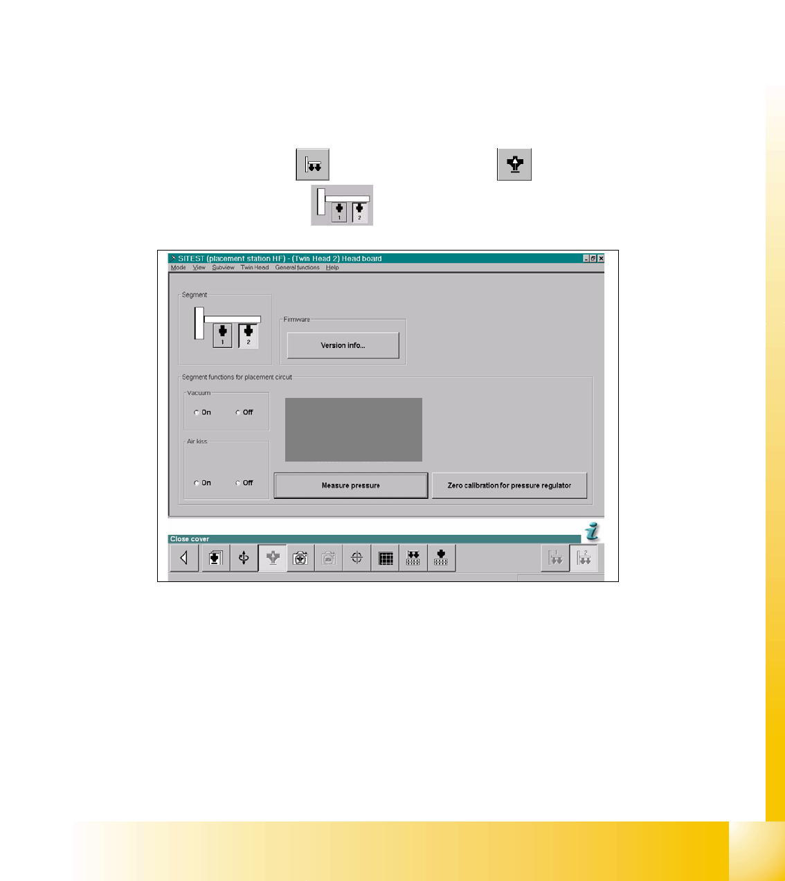
Sitest: 7 ➠ Select "Twin head" ==> Select "Head board"
➠ Select the "Segment"
Fig. 7.4 - 9 SITEST Functions Head board
➠ Close the nozzle of the appropriate Twin module (e.g. by sealing it with your finger tip).
==> Select "Zero calibration pressure regulator"
The following display appears and show the correction values.