SG_FSE_SiplaceHF_HF3_00193901-05_eng.pdf - 第163页
1 - 49 S tudent Guide SIPLACE HF/HF3 Edition 09/2005 4 Servic es to the machine 49 vacuum and air kiss at T win head 4 The vacuum gene ration and the vacu um regulation at the T win head is a fully sophisticated new proc…
1 - 48
Student Guide SIPLACE HF/HF3
4 Services to the machine Edition 09/2005
48
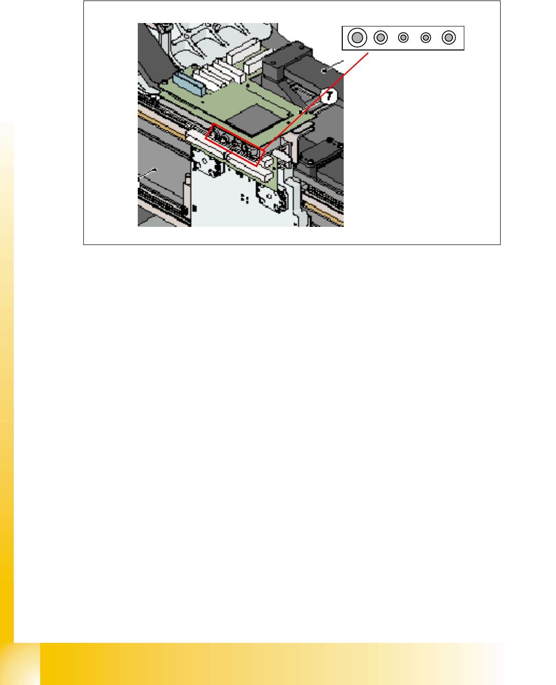
4.3.8.1 Air distribution TWIN-head
4
Fig. 4.3 - 18 air distribution TWIN-head
4
Legend
:
1. sealed
2. air supply TWIN-head segment 1 vacuum-air kiss generator
3. air supply TWIN-head segment 1 Z-axis power fail safety unit
4. air supply TWIN-head segment 2 vacuum-air kiss generator
5. air supply TWIN-head segment 2 Z-axis power fail safety unit
4
4
4
4
4
4
4
4
4
4
1 2 3 4 5
1 - 49
Student Guide SIPLACE HF/HF3
Edition 09/2005 4 Services to the machine
49
vacuum and air kiss at Twin head 4
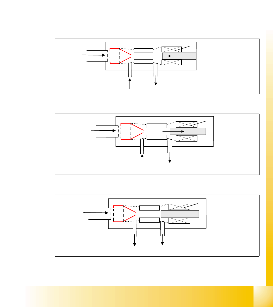
The vacuum generation and the vacuum regulation at the Twin head is a fully sophisticated
new process. The vacuum and air kiss is not anymore seperated, as known from former vac-
uum systems we used. Furthermore, 1 venturi system is used for vacuum and air kiss by con-
trolling it through an adjustable piston. Depending on the position of this piston 3 different
states are to regulate.
4
state 1: normal vacuum generation (max. vacuum) 4
state 2: regulated and controlled vacuum 4
state 3: no vacuum, air kiss in case 4
Fig. 4.3 - 19 TWIN-head max. vacuum
Fig. 4.3 - 20 regulated vacuum
Fig. 4.3 - 21 air kiss
Input compressed
air 4.6 bar
1
2
3
4
air exhaust (open)
max. vacuum
Legend:
1. venturi nozzle
2. plunger for vacuum / airkiss
generation
3. vacuum / airkiss
4. exhaust pipe
Input compressed
air 4.6 bar
1
2
3
4
air exhaust (open)
medium vacuum
Input compressed
air 4.6 bar
1
2
3
4
air kiss air exhaust (blocked)air kiss
1 - 50
Student Guide SIPLACE HF/HF3
4 Services to the machine Edition 09/2005
50
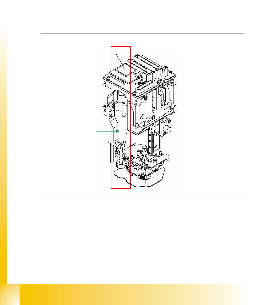
4.3.8.2 Z-axis safety process
Another use of 4.6 bar compressed air is the Z-axis safety process. As long the machine is in a
normal mode, the Z-axis keeps position on zero digits. In case, power drops down, it must be se-
cured, the Z-axis does not remain or fall down in any down position.
This is realized by a spring, which retracts the z-axis to top position by extending. As long as there
is no fault event, the spring is pressed by a 4.6 bar compressed air pressure. In a fault event, like
power drop, the power fail mode is activated, which powers the z-axis for about 200 ms seconds
with the aid of a capacitor, located in the main power supply. This secures the Z-axis moves up
with power and with additional help through retract spring.
Fig. 4.3 - 22 Z-axis retract device
retract device