SG_FSE_SiplaceHF_HF3_00193901-05_eng.pdf - 第128页
1 - 14 S tudent Guide SIPLACE HF/HF3 4 Services to the machine Edition 09/2005 14 4.2.4.2 T ransformer 1 The main re ason for th e transformer T1 is to pow er the X/Y and star axis, protec ted by F4. C on- tactors K2, K3…
1 - 13
Student Guide SIPLACE HF/HF3
Edition 09/2005 4 Services to the machine
13
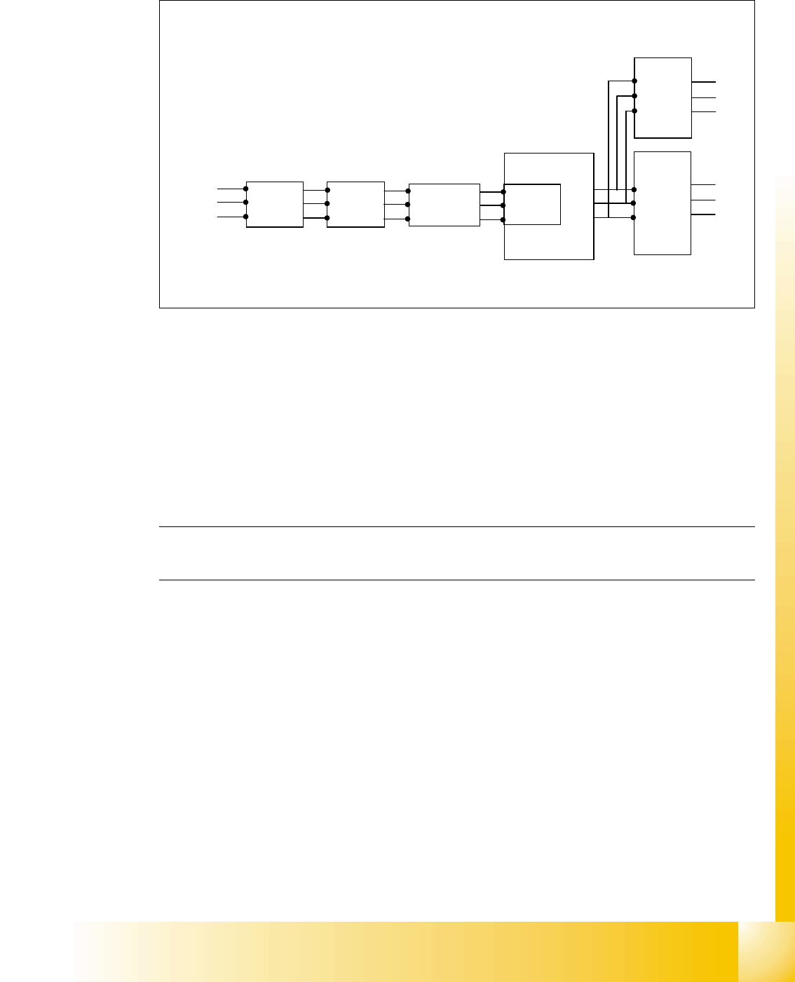
4.2.4.1 Input Voltage
Fig. 4.2 - 5 input voltage
Legend
Q1: main switch
Q2: motor circuit breaker
K1: main contactor and inrush current limiter for T1
T1: transformer 1
T2: transformer 2
Please Note: After the transformer T1 and T2, the main power potential end and only secundary
voltages supply the machine
Q1
Q2
K1
3 phase
U
V
W
T1
U
V
W
T2
3x 230 V
Ínrush current
limiter for T1
L1
L2
L3
power
filter
1 - 14
Student Guide SIPLACE HF/HF3
4 Services to the machine Edition 09/2005
14
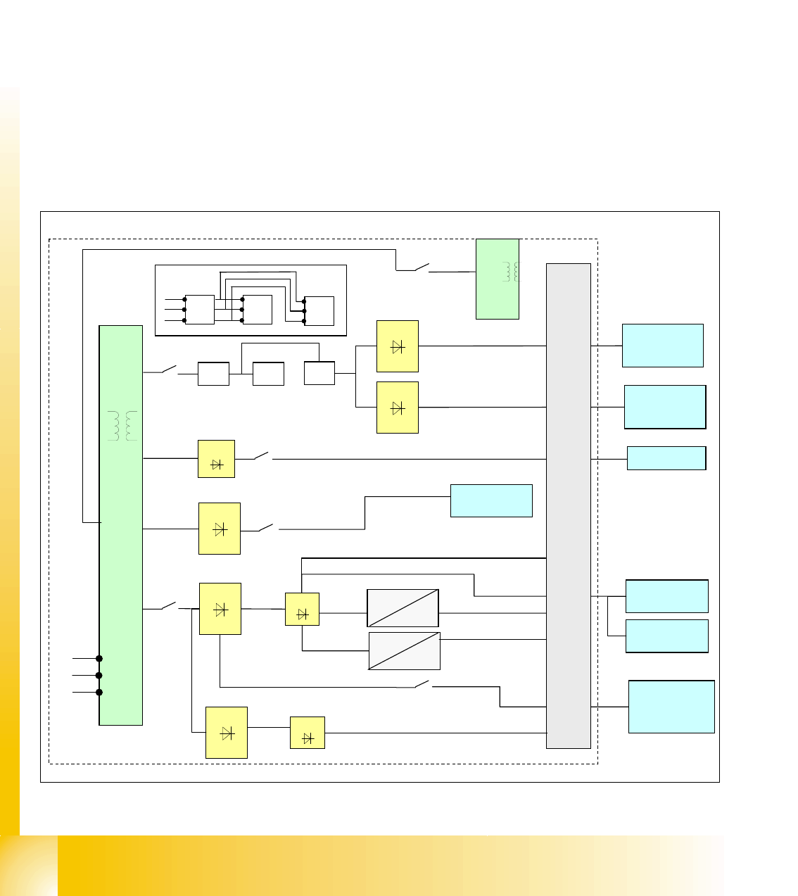
4.2.4.2 Transformer 1
The main reason for the transformer T1 is to power the X/Y and star axis, protected by F4. Con-
tactors K2, K3 and K4 illustrate fixed elements of the electrical safety concept. In a fault event, e.g.
open cover, the servos are disconnected from the energy.
4
The power supply unit provides the following supply voltages: 4
Primary Transformer T1 4
– 250 VDC for the servo amplifiers of the x and y axes.
– 150 VDC servo amplifiers of the star axis.
– 34 VDC for the inrush current limiter servo
– 52 VDC for the DC/DC converters in the main power unit
– 52 VDC for camera illumination and computer unit DC/DC converter
Fig. 4.2 - 6 overview transformer T1
T1
main distributor power supply
X/Y servo
U7
U70
250 VDC
52 VDC
52 VDC
24 VDC
52 VDC
5 VDC
F11
F12
U6
U60
power fail Twin head
U8
F10
34 VDC
K2 K3
K4
F4
K2 K3
K4
U1
U2
F5
U3
150 VDC
X/Y servo
250 VDC
star servo
SZ1 (Inrush
current delay)
3 phase
3 phase
3 phase
3 x 230 V
T2
F7
DC/DC
computer unit
52 VDC
L1
L2
L3
DC/DC axis
unit
camera
illumination
P&P camera
power fail C&P head
main power supply
U 20
U 30
1 - 15
Student Guide SIPLACE HF/HF3
Edition 09/2005 4 Services to the machine
15
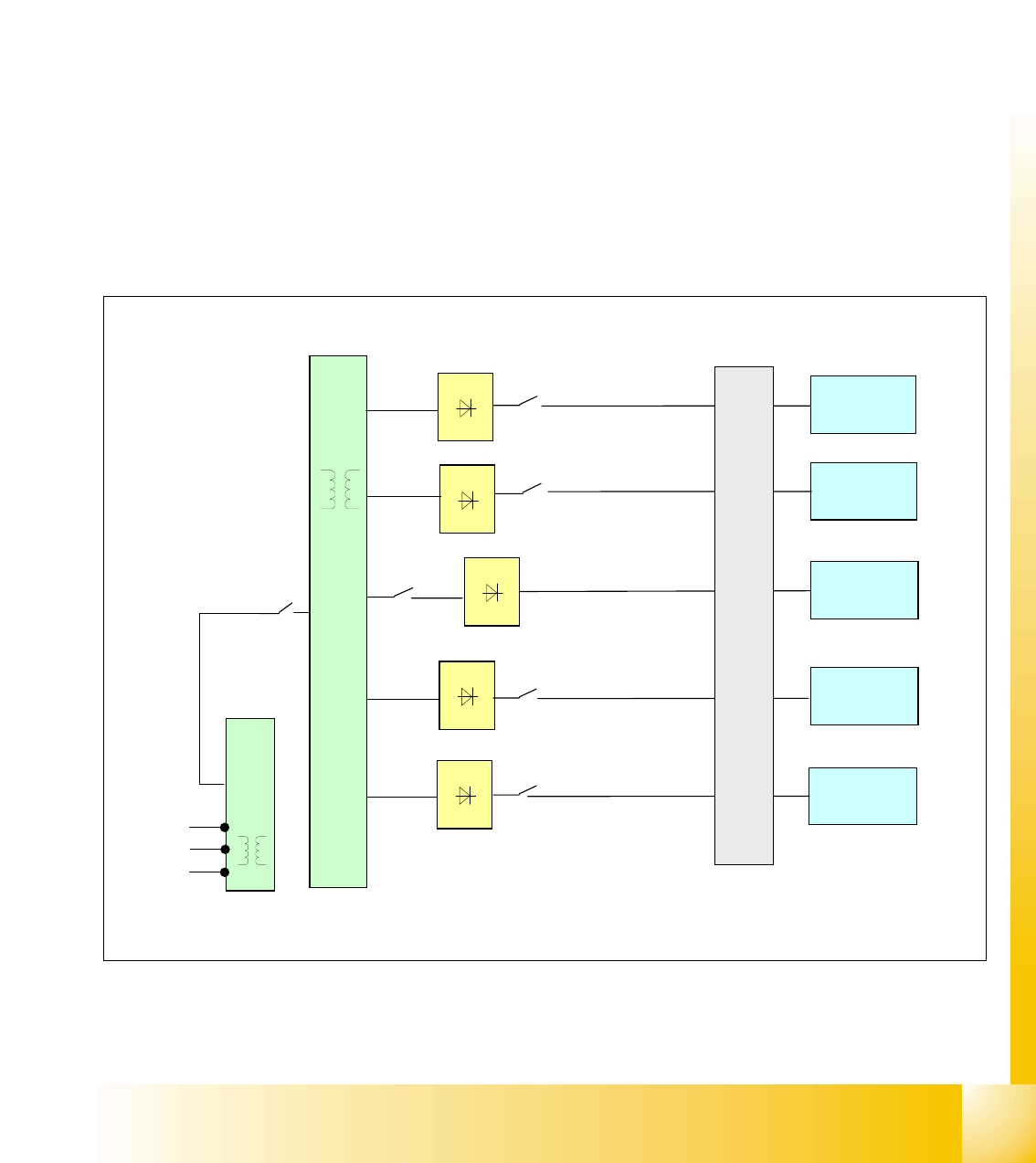
4.2.4.3 Transformer 2
The main reason for the transformer T2 is to power the Z- and Dp servos, protected by F6
4
The power supply unit provides the following supply voltages: 4
Secundary Transformer T2
– 40 VDC for the servo amplifiers the z and dp axes.
– 34 VDC for PCB handling system.
– 40 VDC for the component tables (30 V for feeder operation).
– 10 VDC for the component tables (5 V for logic).
– 28 VDC for the monitor.
– 24 VDC for the Y-axis motor cooling device.
Fig. 4.2 - 7 overview transformer 2
F8
PCB
Transport
Feeder
table
Monitor
cooling
Y-Axis
T1
L1
L2
L3
F7
T2
U4
F6
main power supply distributor
Z/Dp Servo
U5
U9
U10
F2
F13
U11
F14
40 VDC
34 VDC
24 VDC
28 VDC
40 VDC
T1
2
3
0
V