SG_FSE_SiplaceHF_HF3_00193901-05_eng.pdf - 第190页
1 - 24 S tudent Guide SIPLACE HF/HF3 5 Gantry Edition 09/2005 24 5.5.2 Check dynamic X-axis The inspection of dynamics occurs with the following signals: – Deviation of position – Nominal curren t – End signal ( Adap ter…
1 - 23
Student Guide SIPLACE HF/HF3
Edition 09/2005 5 Gantry
23
5.5 Axis control
5.5.1 Parts for the axis control
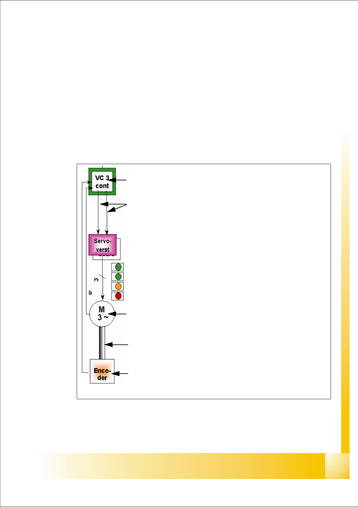
The control loop for control the X- and Y-axis in general consist of the following parts:
– Axis board with VC 3 Controller
– Servo board (TDS)
– 3 Phase AC linear motor
– Measurement system (Incremental scale and encoder)
All linear motors have temperature sensor to protect it against high temperature.
Fig. 5.5 - 1 Parts "Axis control"
Axis board A363 with VC 3 Controller (VC = Velocity Commutation)
Control signals I
soll "W" and I soll "U"
Servo board control directly the linear motor, Intermediate (DC) voltage cir-
cuit is 250V.
LED‘s on Servo board:
– Power supply ON
– Servo enable, it the enable signal from the axis board.
–Display I
RMS limit shorter than 2,5 s.
– Error: Over voltage, -current, -temperature longer than 2,5 sec.
3 Phase AC linear motor X-and Y-axis with integreted temperatur sensor.
Between motor and incremental encoder exist a fixed mechanically connec-
tion.
Incremental encoder: Transmitted the correct position to the axis board and
is the only feedback signal to control the motor (Track signals).
1 - 24
Student Guide SIPLACE HF/HF3
5 Gantry Edition 09/2005
24
5.5.2 Check dynamic X-axis
The inspection of dynamics occurs with the following signals:
– Deviation of position
– Nominal current
– End signal ( Adapter board Axis in target position)
– Actual position = nominal position ( Axis testbox Output end signal)
Please Note:
To check the axis dynamic, please use the "Adjustment manua HF platform".
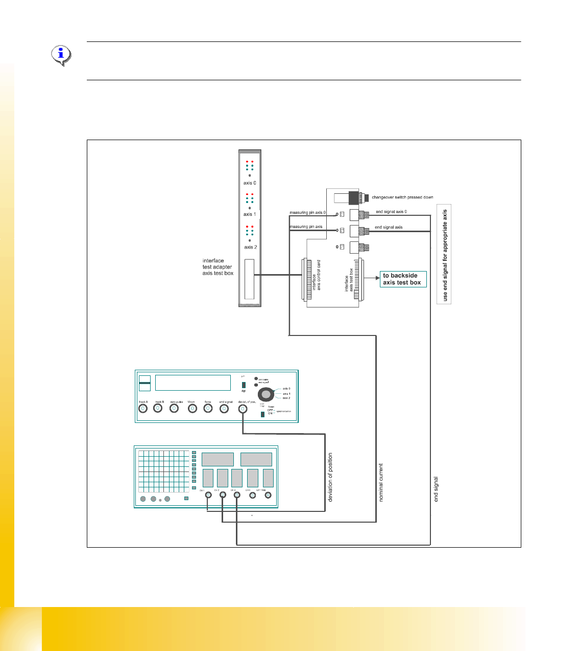
5.5.2.1 Test setup with Axis testbox
Fig. 5.5 - 2 Test setup to check the dynamic ,Gantry
– An additional connector on channel 4 is the actual pos.=nom.pos. signal from the axis testbox.
11
1 - 25
Student Guide SIPLACE HF/HF3
Edition 09/2005 5 Gantry
25
Please Note:
Use an RC - filter to record the current curve.
Measure the end signal on the adapter board "axis test box", with the switch pressed down. 5
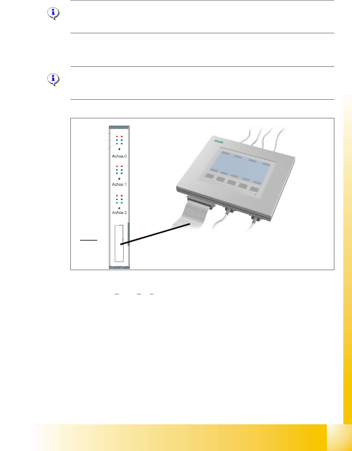
5.5.2.2 Test setup with SAT-Box
Please Note:
The setting on the SAT-Box together with the SITEST -Progam are described in the adjustment
manual. 5
Fig. 5.5 - 3 Test set up SAT-Box
Legend outputs Siplace Axis Tester to oscilloscope channels
On account of the higher accuracy requirements at a gantry with Twin head, may be the X- and Y
axes with different controller parameters compared to a gantry with C&P head operated (see fol-
lowings diagrams).
(1) Nominal current (Vreg)
not connected to the scope for HF
(2) uncommutated nominal current
connect to CH2
(3) Deviation of position connect to CH1 (4) End signal connect to CH 3
Axis unit error
Servo ON
Initialize
Counter error
Zero puls
End signal
Interface:
Test adapter,
Axis test box,
SAT-Box
2
4
1
3