SG_FSE_SiplaceHF_HF3_00193901-05_eng.pdf - 第31页
1 - 5 S tudent Guide SIPLACE HF/HF3 Edition 09/2005 2 Overview 5 Gantry 3 – (HF) Twin head 12- segment C & P head, Twin head or 6-segment C & P head (HF3) – (HF3) Twin head 12-seg ment C & P head, Twin head o…
1 - 4
Student Guide SIPLACE HF/HF3
2 Overview Edition 09/2005
4
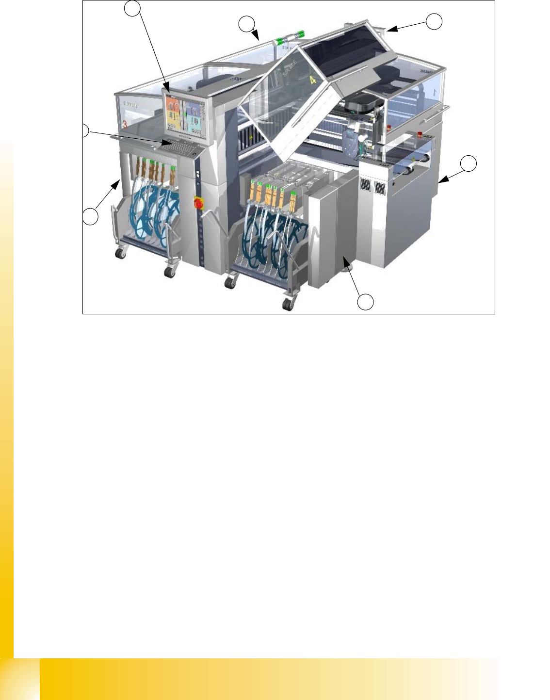
Fig. 2.1 - 2 Overview Siplace HF
Legend:
Two placement methods are used:
–the Collect&Place method with revolver heads for components from size 0201 to fine-pitch
–the Pick&Place method with the SIPLACE TwinHead for fine-pitch and OSC components
The placement machine is based on a torsionally-rigid and vibration-damped cast steel machine
frame. This guarantees an excellent production quality and less environmental pollution for em-
ployees since the noise of shaking and vibration are reduced to a minimum.
The placement machine has two gantries on the HF and three gantries on the HF3. There is a
placement head on each gantry. These can be quickly and accurately positioned by linear motors,
moving independently of one another in the X and Y directions. The following placement head
configuration is currently possible:
Gantry 1
– 12-segment Collect & Place head or -6-segment Collect & Place head or TwinHead (HF)
(7) Monitor (on both side) (8) Keyboard (on both side)
(9) Location 1 (10) Location 2
(11) Location 3 (12) Location 4
1
1
2
4
3
5
6
1 - 5
Student Guide SIPLACE HF/HF3
Edition 09/2005 2 Overview
5
Gantry 3
– (HF) Twin head 12-segment C & P head, Twin head or 6-segment C & P head (HF3)
– (HF3) Twin head 12-segment C & P head, Twin head or 6-segment C & P head
Gantry 4 (HF3)
– (HF3) 12-segment Collect & Place head or 6-segment Collect & Place head
According to the head modularity principle developed by Siemens, the placement heads can be
quickly and easily changed.
There are four locations for feeding components. Up to four component trolleys or alternatively
one or two matrix tray changers can be docked in place of component trolleys on the HF machine
and one matrix tray changer on the HF3 machine.
The placement heads fetch the components from the fixed feeders on the component cart or from
the trays in the matrix tray changer, and place the PCBs, which are also stationary. Each place-
ment head has its own processing area at HF machine.
– On the single conveyor, this is a placement area for each placement head with one conveyor.
So one or two PCBs can be placed simultaneously in the machine.
– On the dual conveyor, there are two placement areas with two conveyors for each placement
head. So up to four PCBs can be placed simultaneously.
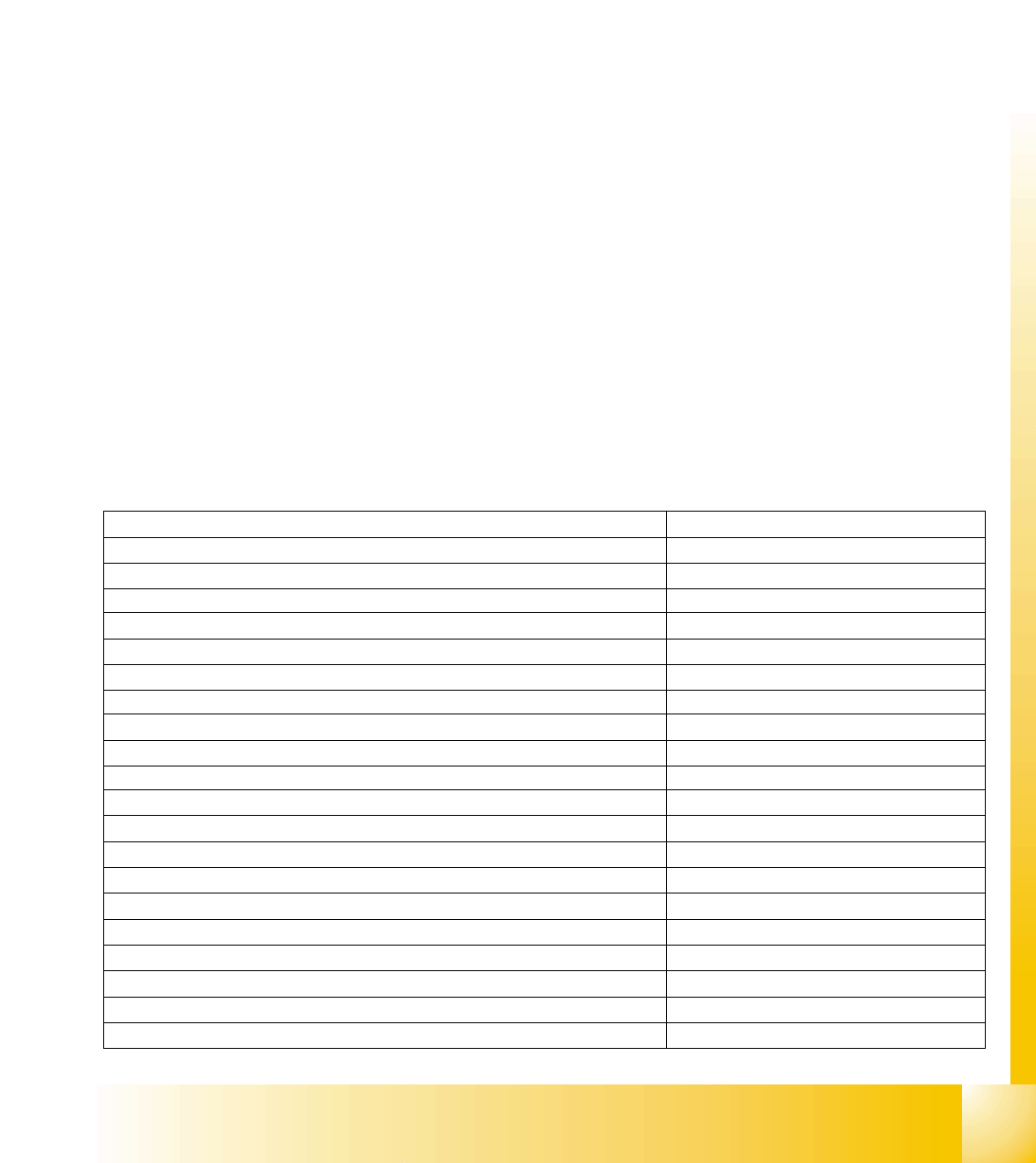
2.1.1 Specification and Configuration Siplace HF/HF3
Placement Speed Head configuration C&P12 / TH 17000 cph
Placement Speed Head configuration C&P6 / TH 12000 cph
Placement Speed Head configuration TH / TH 7000 cph
Placement Accuracy C&P12 (4 sigma) 60 µm
Placement Accuracy C&P6 (4 sigma) 60 µm
Placement Accuracy Twin Head (4 sigma) 35 µm
Number of feeder tables 4
Number of slots per feeder table 15
Head Modularity
Gantry 1(HF) 12C&P ,6 C&P or Twin head
Gantry 3 (HF,SW505) 12C&P ,6 C&P or Twin head
Gantry 1(HF3) 12C&P or 6 C&P
Gantry 4 (HF3) 12C&P or 6 C&P
Gantry 3 (HF3) 12C&P , 6 C&P or Twin head
C&P12 and C&P6 specification see chapter C&P head
Maximum component height 12 C&P head 6,0 mm
Maximum component height 6 C&P head 8,5 mm
Maximum component height Twin Head 25 mm
1 - 6
Student Guide SIPLACE HF/HF3
2 Overview Edition 09/2005
6
This data are a basic information on HF-specification. For the actual valid secification data see
’Scope of delivery’ document.
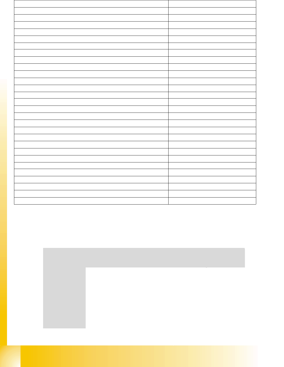
Overview Head Modularity and Benchmark performance HF 3 machine 2
Nozzle distance Twin head 70.8 mm
Maximum component size both nozzle operation 50 x 50 mm (69 x 10 mm)
Maximum component size single nozzle operation 85 x 85 mm (125 x 10 mm)
Placement force 1 - 15 N
Maximum component weigth standard 30 g
Maximum component weigth with restrictions 100 g
Maximum component size stationary camera (single shot) 40 x 50 mm
Resolution stationary camera 79 µ / pixel
Minimum Bump diameter 320 µm
Maximum component size stationary Flip Chip camera (single shot) 8 x 8 mm
Resolution stationary Flip Chip camera 19 µ / pixel
Minimum Bump diameter 80 µm
PCB widths Single conveyor 50 - 508 mm
Maximum PCB lengths Single conveyor (Long Board Option) 50 - 450 mm (610)
Maximum PCB widths Dual conveyor (Single mode operation) 2 x 50 - 250 mm (450mm)
Maximum PCB lengths Dual conveyor (Long Board Option) 50 - 450 mm (610)
PCB thickness 0.3 - 4.5mm
PCB conveyor speed 50 -450 mm/s
Maximum PCB weigth 3 kg
PCB edge clearance 3 mm
PCB changeover time < 2.5 s
Machine size (L x W) 2380 x 2525mm
Heigth of PCB transport 830 - 950mm +/- 15mm
Compressed air pressure 5 - 8 bar
Compressed air consumption RV12/TH or RV6/TH ~ 350 NL/min.
Compressed air consumption RV12/12 ~ 450 NL/min.
Siplace HF3
Placement area 1
Gantry
1 4
Placement area 2
Gantry
2 3
Benchmark per-
formance
( cph )
12 12 - 12
40.400
6 6 - 6
27.600
12 12 - 6
35.700
12 6 - 6
29.600
6 12 - 6
29.600
12 12 - TH
30.100
12 6 - TH
24.000
6 12 - TH
24.000
Placement
head
Configuration
6 6 - TH
22.000