SG_FSE_SiplaceHF_HF3_00193901-05_eng.pdf - 第329页
1 - 17 S tudent Guide SIPLACE HF/HF3 Edition 09/2005 7 TWIN-Head 17 7.3.7 Prep are placement 2nd component 7.3.7.1 Place 2nd component – S tart X / Y Axis to the real placement positio n (inclusive cor- rection coordina …
1 - 16
Student Guide SIPLACE HF/HF3
7 TWIN-Head Edition 09/2005
16
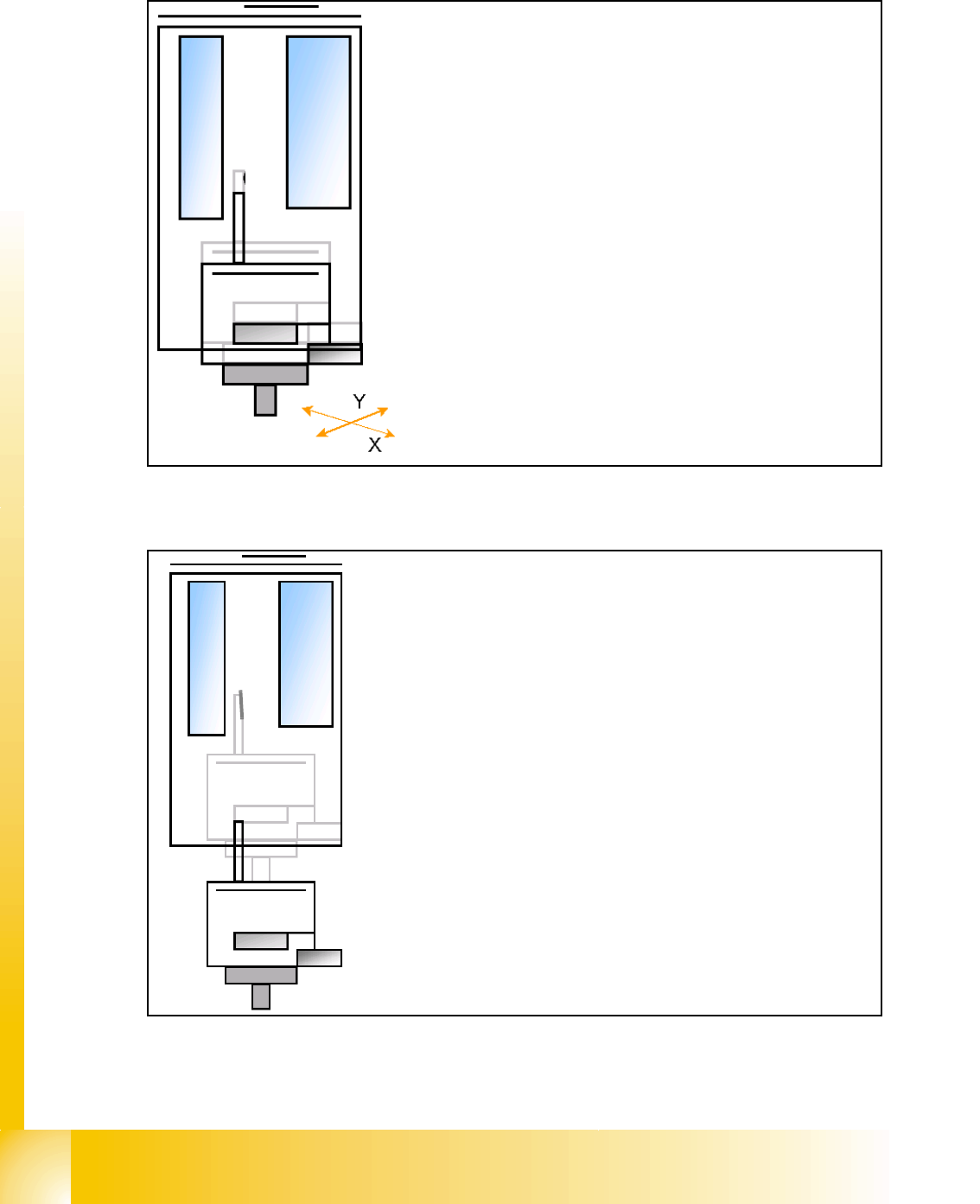
7.3.6 Prepare placement 1st component
7.3.6.1 Place 1st component
– Move X / Y Axis correction coordinates
– Start D- Axis to correct component angle to precise place-
ment angle
– Z-Axis position downwards with Standard profile (or any
other programmed profile up to 15N) for placement force 2N.
– The Force increase up to the programmed level after contact
of the component on the PCB.
– With this Force signal the End signal is set. The air kiss con-
trol is activated too.
– At Air kiss level for placement ..
– .. Z-Axis move upwards with Standard profile.
– Prepare placement 2nd component.
1 - 17
Student Guide SIPLACE HF/HF3
Edition 09/2005 7 TWIN-Head
17
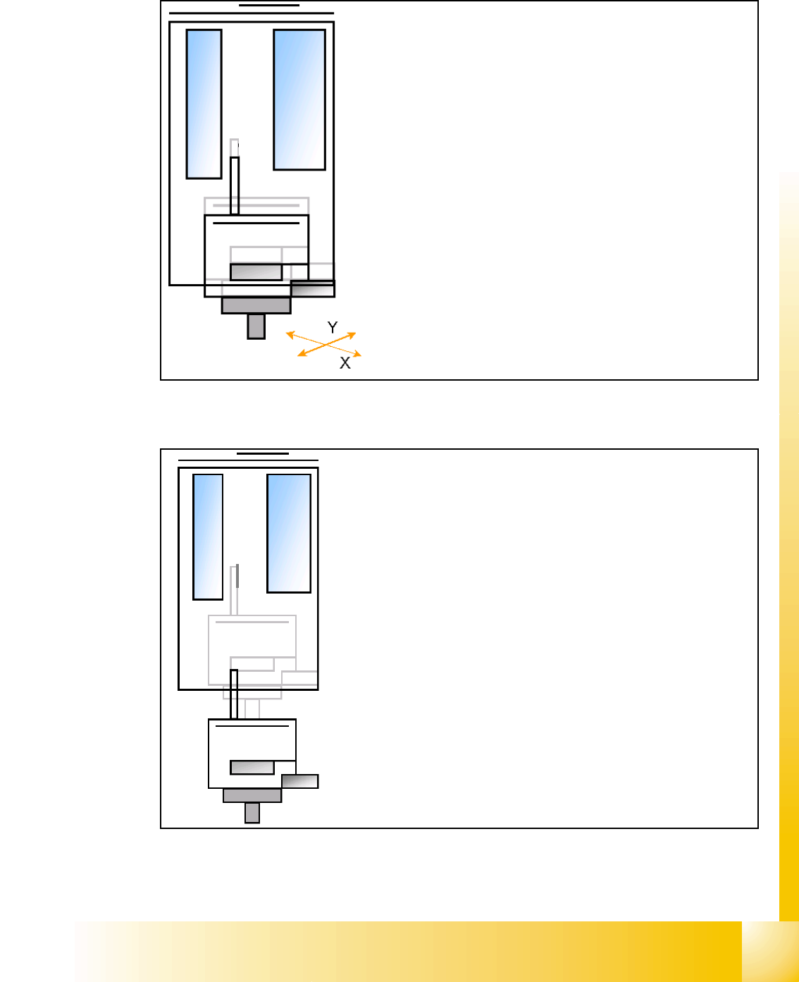
7.3.7 Prepare placement 2nd component
7.3.7.1 Place 2nd component
– Start X / Y Axis to the real placement position (inclusive cor-
rection coordinates).
– Start D- Axis to correct component to precise placement an-
gle
– Z-Axis position downwards with Standard profile (ôr any
other programmed profile up to 15N)for placement force 2 N.
– The Force increase up to the programmed level after contact
of the component on the PCB.
– With this Force signal the End signal is set. The air kiss
control is activated too.
– At Air kiss level for placement Z-Axis move upwards with
Standard profile.
– The next Pick up sequence is prepared for module 1.