SG_FSE_SiplaceHF_HF3_00193901-05_eng.pdf - 第154页
1 - 40 S tudent Guide SIPLACE HF/HF3 4 Services to the machine Edition 09/2005 40 4.3.3.4 Main V alve , main regulator X59 for machine component s After the machine is switched on with the main switch, the valve is power…
1 - 39
Student Guide SIPLACE HF/HF3
Edition 09/2005 4 Services to the machine
39
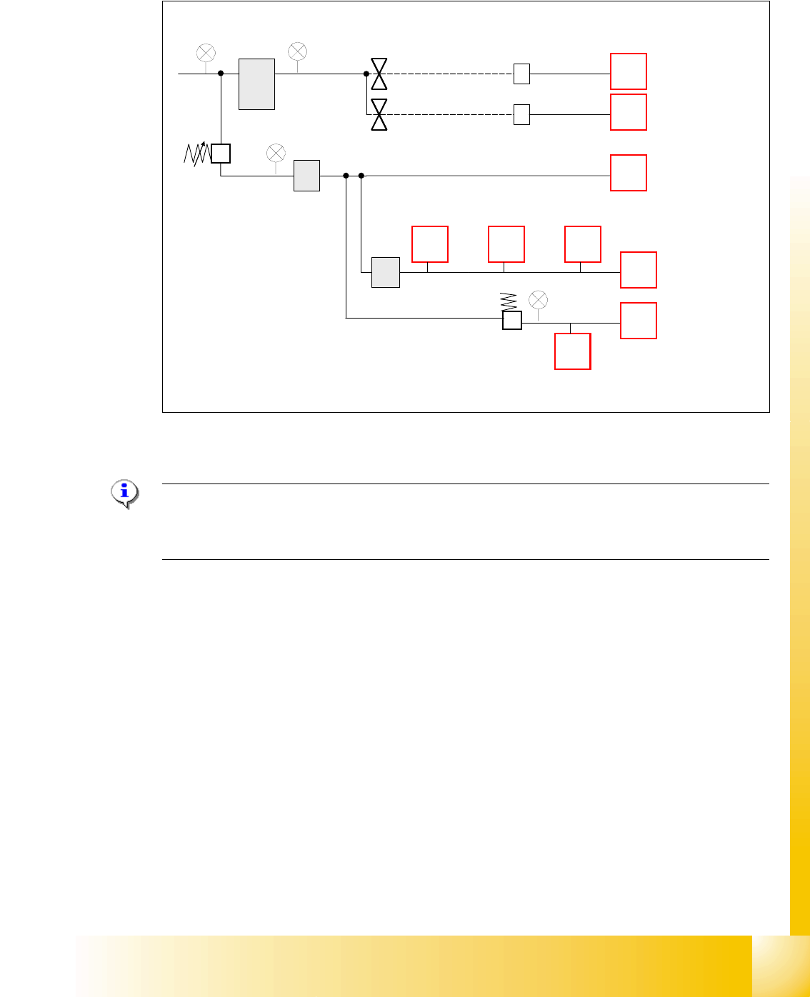
4.3.3.3 Switch on Sequency Pneumatic Units
Fig. 4.3 - 6 switch on sequency pneumatic
Please Note: Prop. valve X58, controlled by relay K2, is immediately powered with machine ON.
After the reference run is performed, the valve X58 can be switched off by soft-
ware (as a standard 2 minutes).
The time to deactivate the prop. valve can be changed in station software
4
– settings
– configure compressed air deactivation
– switch off after 1-60 minutes
5-10 bar
4,6+-0.1bar
2,5 ± 0,5 bar
proportional
valve (controlled
by K2)
main valve, ON with
power on (controlled by K1)
safety valve, ON/OFF
8controlled by SSK)
placement head 1
docking station
(co-table 1-4)
placement head 2
tape cutter 1-4
PCB transport,
lifting table
PCB transport,
width adjustment
PCB stopper’ long
board option’
nozzle changer
C&P head
bulk case option
X58
X59
X60
1 - 40
Student Guide SIPLACE HF/HF3
4 Services to the machine Edition 09/2005
40
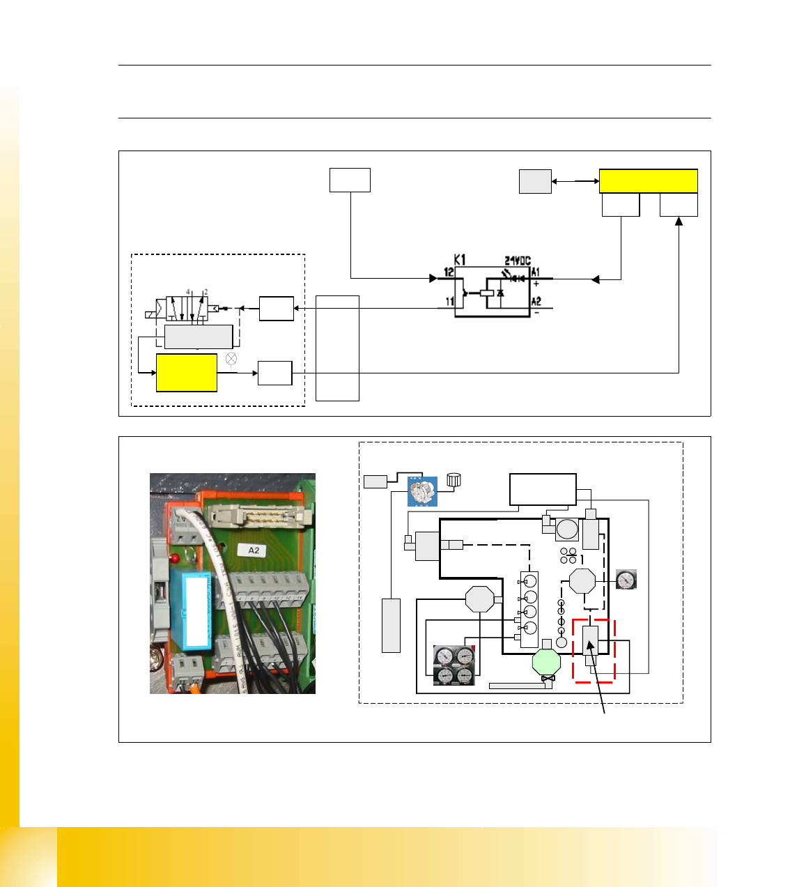
4.3.3.4 Main Valve , main regulator X59 for machine components
After the machine is switched on with the main switch, the valve is powered and air runs into the
system. Opening any cover, for e.g, has no effect to the air supply. Only when the 24V power is
missing or the machine is switched off, the valve close and
no air is supplied to the docking sta-
tion (co-table), as well as via X60 to the tape cutter and PCB transport system. If the pressure is
too low, the A/D converter provides an output of 24 VDC. This signal is supplied via the CAN I/O
module in section 4 (pressure too low) and via the CAN bus to the machine controller. The valve
X59 is controlled by K1, located in section 4, sub-distributor.
The pressure for this 5/2 valve is manually adjusted by a throttle to 5 +0.1 bar.
NOTE: This main pressure regulator can be damaged if the machine is turned on without com-
pressed air supplied. Therefore if the compressed air supply fails, turn of the machine.
Fig. 4.3 - 7 Relay K1 section 4 and main valve
main valve
pressure
sensor
X20ra
24 V
CAN I/O section 4
X7rb
output valve OFF
GND
air ON / OFF
X3rb
input message pressure too low (threshold 4.5 bar)
X1ra
MC
X59
X59
power supply 24 V
section 4, relay K1
K
1
main valve
main pneumatic unit
1 - 41
Student Guide SIPLACE HF/HF3
Edition 09/2005 4 Services to the machine
41
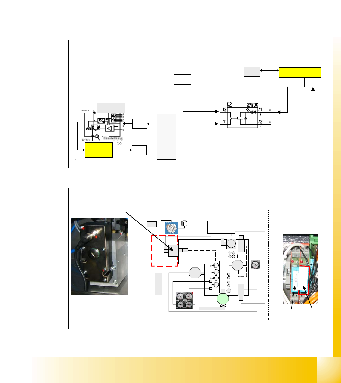
4.3.3.5 Proportional valve, proportional regulator X58
When switching the machine on at the main switch, air is supplied to all placement heads.
After the reference run is performed, the air can be switched of by software after a certain time
(as standard 2 min.) and no air run through the vacuum system of the placement heads.
It automatically regulates the internal machine pressure to 4.8 +0.1 bar for the placement heads.
Included within this regulator block is a pressure sensor which monitors the outgoing air pres-
sure. If the pressure is too low, the A/D converter provides an output of 24 VDC. This signal is
supplied via the CAN I/O module in section 4 (pressure too low) and via the CAN bus to the
machine controller. The valve is controlled by relais K2, located in section 2, main distributor,
relay K1 is not used.
Fig. 4.3 - 8 proportional valve X59 ON/OFF process
Fig. 4.3 - 9 poroportional valve in main pneumatic unit
X7qb X4qb
X21qa
24 V
CAN I/O section 2
o
u
t
p
u
t
v
a
l
v
e
OF
F
GND
power supply 24 V
air ON / OFF
input message pressure 4.5 +O.K
X1qa
MC
prop. valve
pressure
sensor
X58
X58
Main pneumatic unit,
proportional valve
Main pneumatic unit
Section 2, relay K2
Relay
K2
K
2
Relay K1
(not used)