SG_FSE_SiplaceHF_HF3_00193901-05_eng.pdf - 第407页
1 - 21 S tudent Guide SIPLACE HF/HF3 Edition 09/2005 9 Modular conveyor 21 Fig. 9.2 - 10 Setting the actuator block for the width adjustment Legend ➠ This setting must be repeated for all the conveyor rails. 9.2.5.2 Sett…
1 - 20
Student Guide SIPLACE HF/HF3
9 Modular conveyor Edition 09/2005
20
9.2.5 Width adjustment unit (Driver)
9.2.5.1 Setting the BERO on the driver
The BERO (3) (see Fig. 9.2 - 9) provides a signal for controlling the pneumatic valve of the driver.
Once the switching point ’conveyor rail reached’ is reached, the pneumatic valve engages the
conveyor rail.
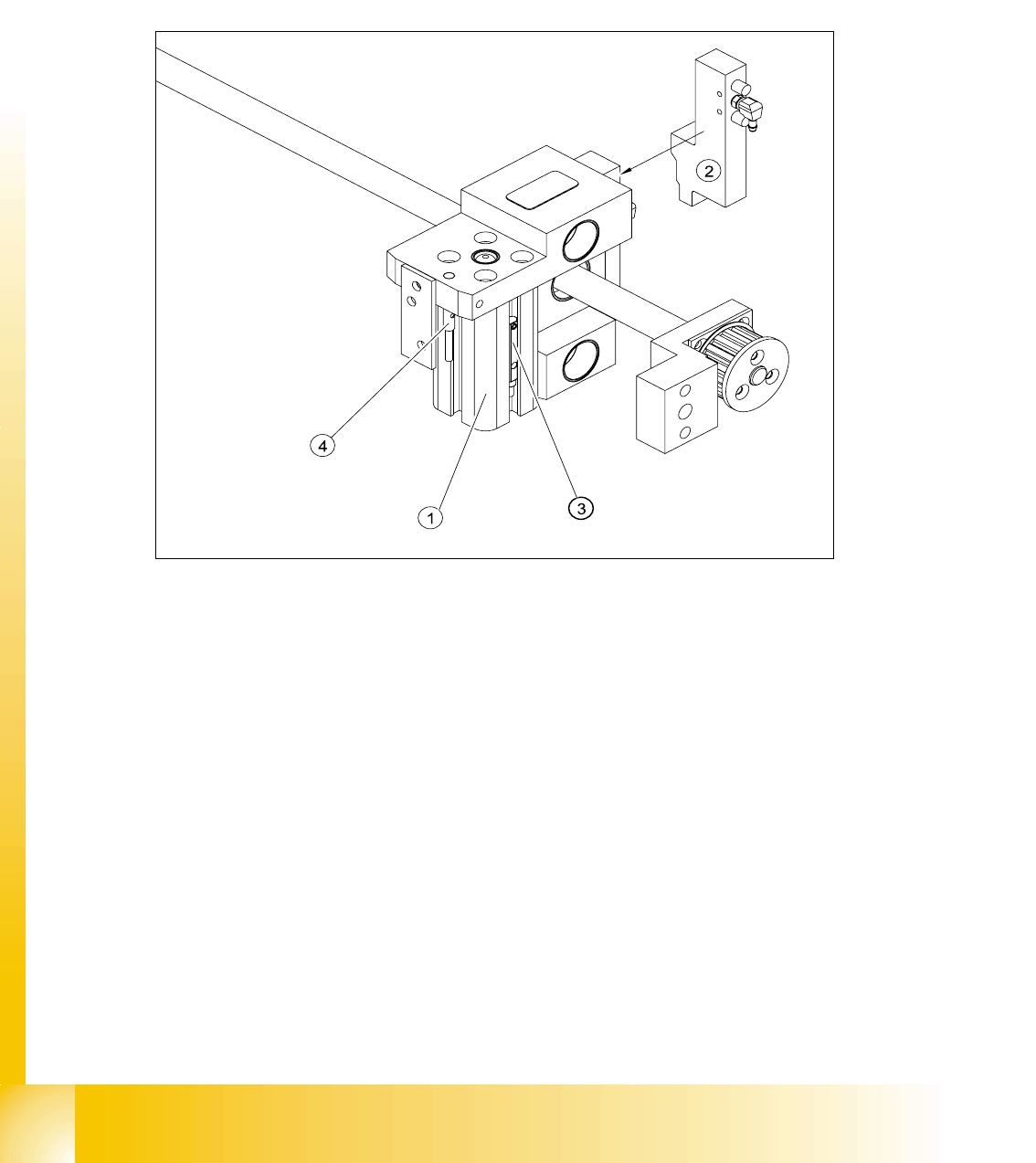
Fig. 9.2 - 9 Overview of the BEROs on the driver for width adjustment
Legend to Fig. 9.2 - 9:
Setting Bero and actuator for transport rail position: 9
➠ When the BERO (4) is installed, it must not protude the driver.
➠ The switching point is set via the actuator on the conveyor rail
➠ Move the driver under the conveyor rail, then loosen the actuator using the screw.
➠ Place the driver at the final dimension of 2/10 mm, press the actuator onto the final dimension
and fix with the screw.
➠ Actuators on all conveyor rails have to be checked and maybe adjusted.
➠ Start SITEST and Calibrate transport.
(1) Short stroke cylinder (2) Solenoid valve
(3) BERO, pneumatic cylinder extended pos. (4) BERO, driver for transport rail position
1 - 21
Student Guide SIPLACE HF/HF3
Edition 09/2005 9 Modular conveyor
21
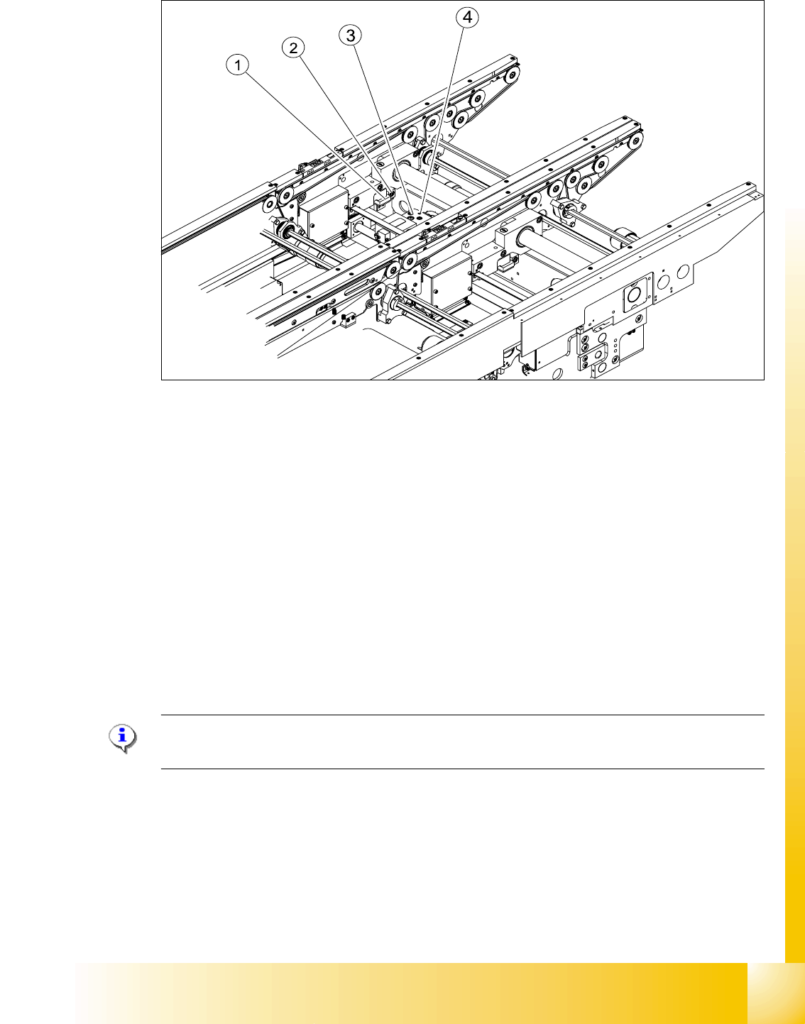
Fig. 9.2 - 10 Setting the actuator block for the width adjustment
Legend
➠ This setting must be repeated for all the conveyor rails.
9.2.5.2 Setting the ’pneumatic cylinder BERO’ on the driver
The BERO (3) (see Fig. 9.2 - 9) on the driver cylinder is designed to switch when the pin of the
driver is extended by the pneumatic cylinder so that the conveyor rail is engaged. This signal en-
ables the width adjustment motor.
Procedure: 9
Please Note:
The BERO on the pneumatic cylinder is set in the engaged state (but not in the free space!).
➠ Start SITEST
➠ Set any conveyor width. This moves the drivers directly under the conveyor rail.
➠ Start the I/O menu.
➠ Activate the pneumatic cylinder.
➠ Set the BERO on the pneumatic cylinder so that the LED (H35/H36/H37 TSP 301) lights up in
the engaged state (see Fig. 9.2 - 9).
(1) Actuator (2) Actuator fixing screw
(3) Driver (4) BERO, driver Transport rail position
1 - 22
Student Guide SIPLACE HF/HF3
9 Modular conveyor Edition 09/2005
22
9.2.6 Setting and checking the laser light barrier for the stopper position
Danger:
Laser beams of laser class 2 occur at the laser light barrier transmitters, so no additional protective
measures are required.
You should never look into the laser beam, however.
Do the adjustment of the LASER Diode Beam direction only from the rear side of the LASER (left
machine side). Keep right side machine covers closed!
The laser beam deflection has greatest effect at the maximum conveyor width, it should always
be calibrated at the maximum conveyor width.
Please Note:
Check or reteach the PCB reference corner after adjustment of the laser light barrier!
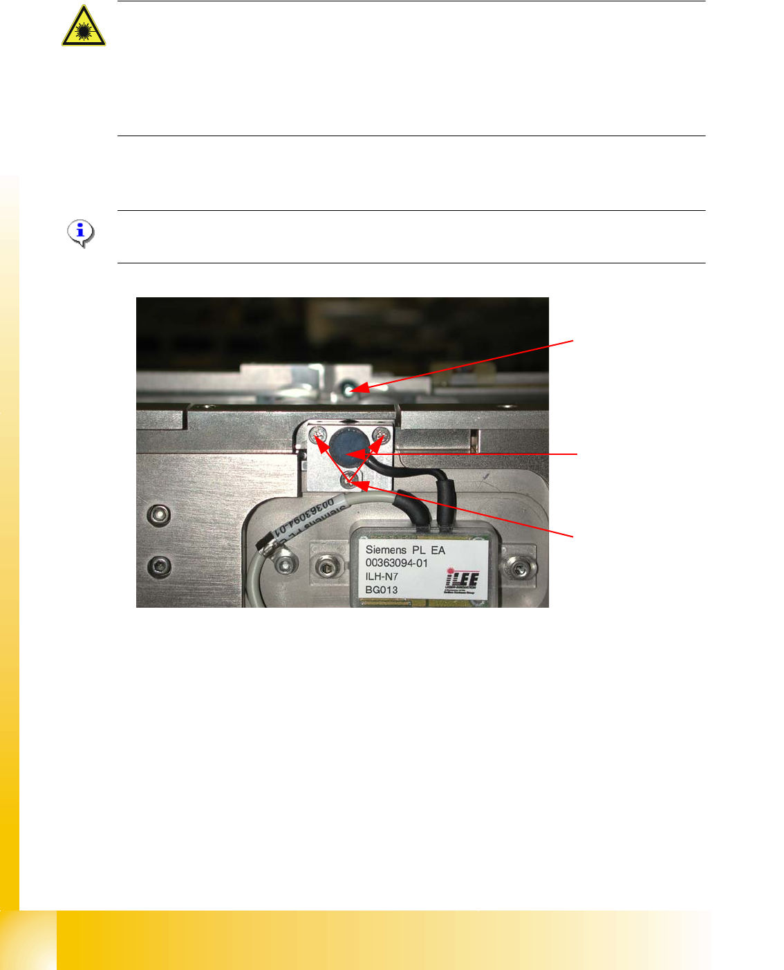
Fig. 9.2 - 11 Laser light barrier
Procedure:
➠ Set the maximum conveyor width.
➠ Choose General functions --> Cycle mode --> Safety mode switch on.
➠ Activate the relevant laser diode using the input/output functions in SITEST.
➠ Check the course of the laser beam. You can make the laser beam visible using a light-colored
PCB or a white sheet of paper (see Fig. 9.2 - 12).
➠ If necessary, use the adjusting screws to set the laser beam to the center of the receiver.
➠ Check the PCB reference corner and reteach, if necessary.
Laser diode
Laser receiver
Adjusting screws
3X