SG_FSE_SiplaceHF_HF3_00193901-05_eng.pdf - 第317页
1 - 5 S tudent Guide SIPLACE HF/HF3 Edition 09/2005 7 TWIN-Head 5 7.2 Reference Run TWIN-head The TWIN-head consist of two s egments wh ich have 2 axes Z and D and the X and Y axes at the Gantry . Before you start the re…
1 - 4
Student Guide SIPLACE HF/HF3
7 TWIN-Head Edition 09/2005
4
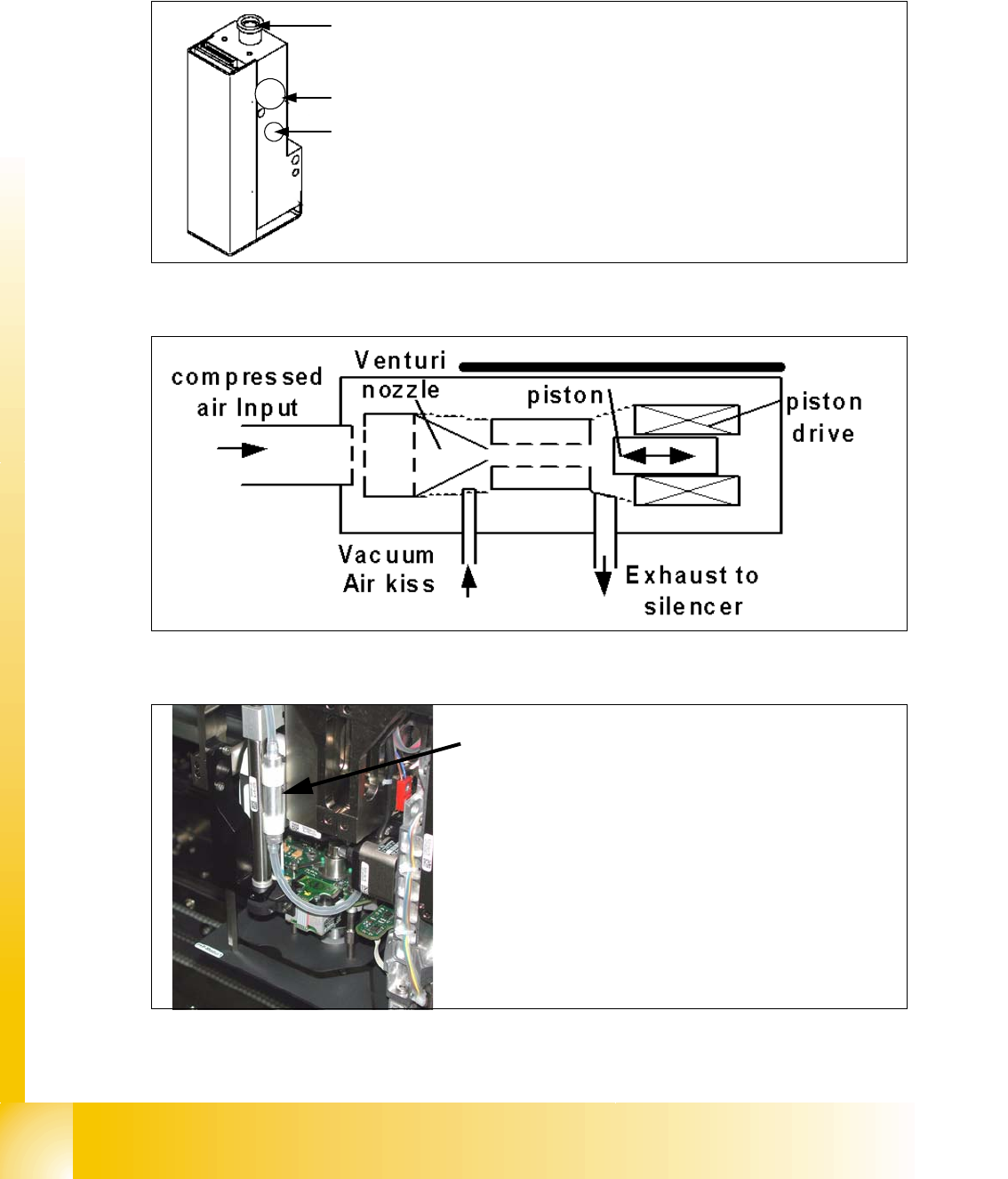
7.1.2.1 Vacuum generator TWIN- Head
The vacuum generator controls the vacuum, air kiss and the zero balancing position (middle Po-
sition-->no vacuum and no air kiss) for the segments with a aid of a linear motor automatically.
Fig. 7.1 - 4 Vacuum generator
Fig. 7.1 - 5 Principle of the vacuum generator
Fig. 7.1 - 6 Filter for the vacuum generator
1
3
2
1. Compressed air input
2. Exhaust air to the silencer and cooling the X-linear motor
3. Output vacuum that go to the D-axis motor through the
shaft of the motor and then to the nozzle.
Filter for the vacuum system on the TWIN- head.
The Filter is mounted on the retract unit and used as an
attenuator to control the vacuum. Together with the defi-
ned length of the silicon pipe reduce the attenuator the
oscillation of the vacuum generator and guaranteed an
accurate vacuum- and air kiss supply.
1 - 5
Student Guide SIPLACE HF/HF3
Edition 09/2005 7 TWIN-Head
5
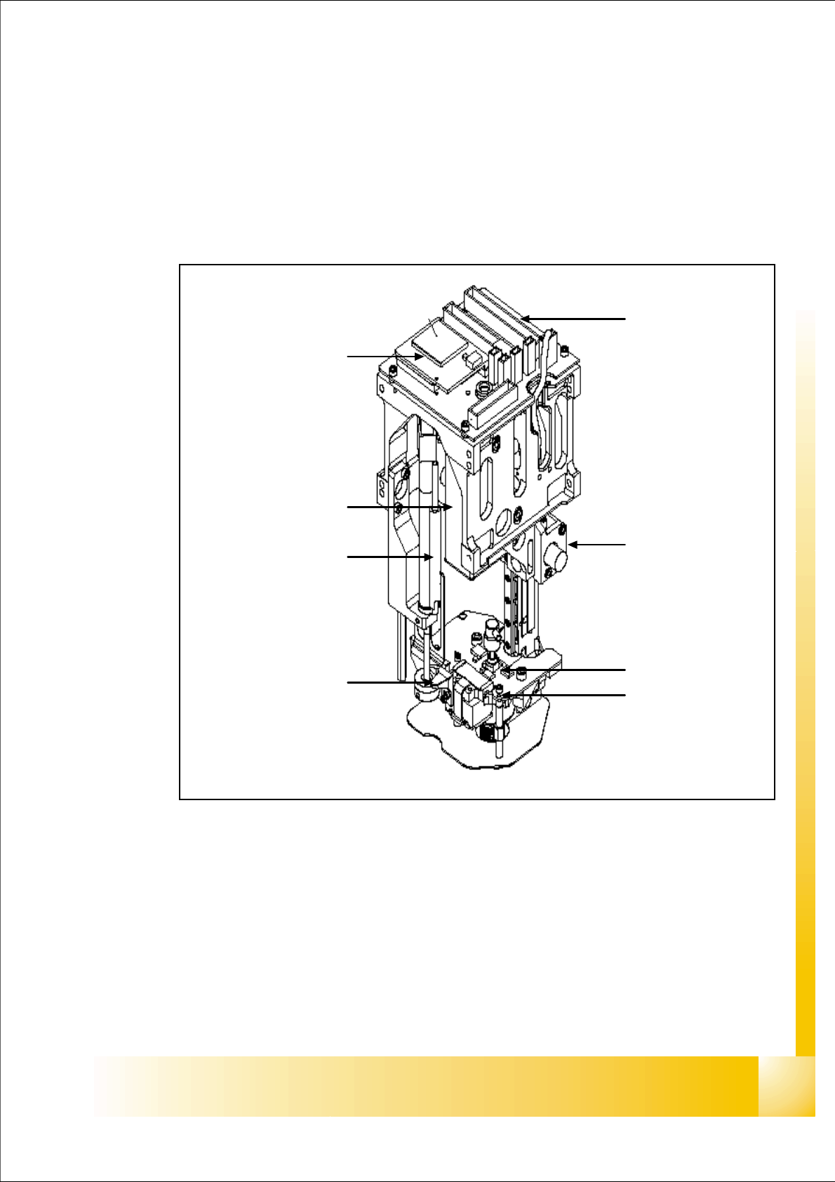
7.2 Reference Run TWIN-head
The TWIN-head consist of two segments which have 2 axes Z and D and the X and Y axes at the
Gantry.
Before you start the reference run the retract cylinder move out to the lower home position. On
both modules the vacuum is on, until the vacuum generator is initialized.
Fig. 7.2 - 1 TWIN-head Z,D- axes
1. Z-axis incremental encoder
2. Z-axis linear incremental scale
3. D-axis incremental encoder with incremental glass scale
4
3
2
5
1
6
7
7
1 - 6
Student Guide SIPLACE HF/HF3
7 TWIN-Head Edition 09/2005
6
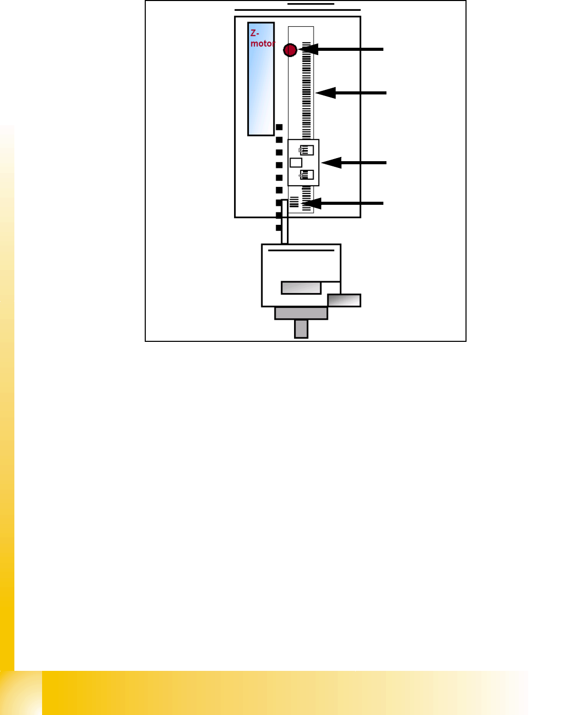
7.2.1 Reference run at Z axis
Fig. 7.2 - 2 Reference run Z-axis
1. Bero Z-axis up (not used)
2. Incremental scale mounted on moveable part of the Z-Axis
3. Fixed Incremental encoder
4. Zero puls on the incrementale scale (only one for Z-axis)
– Z-Axis search for the commutation point of the linear motors (in a special mode because of the
danger of a movement downwards). (A 3 phase motor move on and on when the current is
switched from 1 phase to the next one, at the correct time and in the correct sequence).
– First one of the phases is connect to the power supply. With the incremental encoder the
movement is measured.
– Than the current is switched to the next phase and this movement is measured too. The ma-
chine repeat this to check the measurement values.
– Then the Z-Axis move upwards to the Zero pulse and load the zero point correction.
1
2
3
4