SG_FSE_SiplaceHF_HF3_00193901-05_eng.pdf - 第404页
1 - 18 S tudent Guide SIPLACE HF/HF3 9 Modular convey or Edition 09/2005 18 9.2.4 Checking the limi t switch position ➠ Check the minimum and maximum wid th and ensu re that the conveyor rails are p arallel. Settings: Mi…

1 - 17
Student Guide SIPLACE HF/HF3
Edition 09/2005 9 Modular conveyor
17
9.2.2.3 Procedure to put back single conveyor mode:
➠ Use SITEST (505) transport menu ’options and configuration’ to put ’widen conveyor’ back to
standard.
➠ The moveable conveyor rail of conveyor 1 (right side fixed (track 1 left side fix)) is moved to a
small conveyor width.
➠ The SITEST SW ask to disconnect the lifting tables - Do so-.
➠ The SITEST SW move now with transportcontroll SW the fixed rail of conveyor 2 (right side
fixed (track 1 left side fix)) back to the standard position.
➠ Now adjust conveyor width of both tracks to desired values.
9.2.3 Move fixed conveyor rail for ’extended conveyor’
Please Note: This mode of a flexible conveyor at HF/X is available at single or at dual conveyor.
The standard position of fixed conveyor rail(s) are defined according the settings of X4- / X3- and
X2-machines. Because of the space on pure HF-lines a single conveyor can have up to 509 mm
wide boards; a dual conveyor up to 250 mm on each track.
➠ Use SITEST (505 or higher) transport menu ’options and configuration’ and ’extend conveyor’.
➠ The fixed conveyor rail of conveyor 2 (right side fixed (track 1 left side fix)) remain at its position
➠ The ’fixed conveyor of track 1(right side fixed (track 2 left side fix)) is moved 34mm outside.
This allow the wider boards. The moveable side of track2 (track 1-left side fix) could be set now
to more than 216 mm wide boards.
1 - 18
Student Guide SIPLACE HF/HF3
9 Modular conveyor Edition 09/2005
18
9.2.4 Checking the limit switch position
➠ Check the minimum and maximum width and ensure that the conveyor rails are parallel.
Settings:
Minimum width:49.7 mm
Maximum width, single conveyor:508.5 mm
Maximum width, dual conveyor:250.5 mm (When the fixed conveyor rail is extended)
Maximum width, dual conveyor:216.5 mm (Standard)
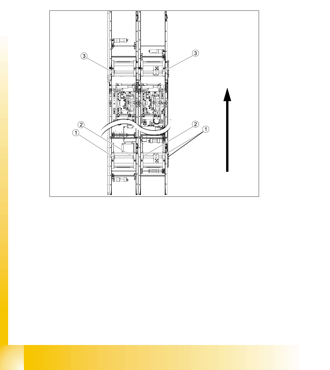
Fig. 9.2 - 7 Position of the width adjustment and conv. rail limit switches (symbolic draw)
Legend
– Limit switches on the input conveyor: There are 5 limit switches below the conveyor rails near
the input conveyor. The limit switches are intended to prevent the conveyor rails moving to-
gether or against the basic conveyor frame.
– Limit switches on the output conveyor: There are 2 limit switches for the driver near the output
conveyor. They serve to protect the traveling range and initialize (right side) the driver for the
width adjustment.
(1) Limit switch on the input conveyor - fitted
below the conveyor rail
(2) Limit switch on the input conveyor - fitted
below the conveyor rail
(3) Limit switch for the width adjustment unit
1 - 19
Student Guide SIPLACE HF/HF3
Edition 09/2005 9 Modular conveyor
19
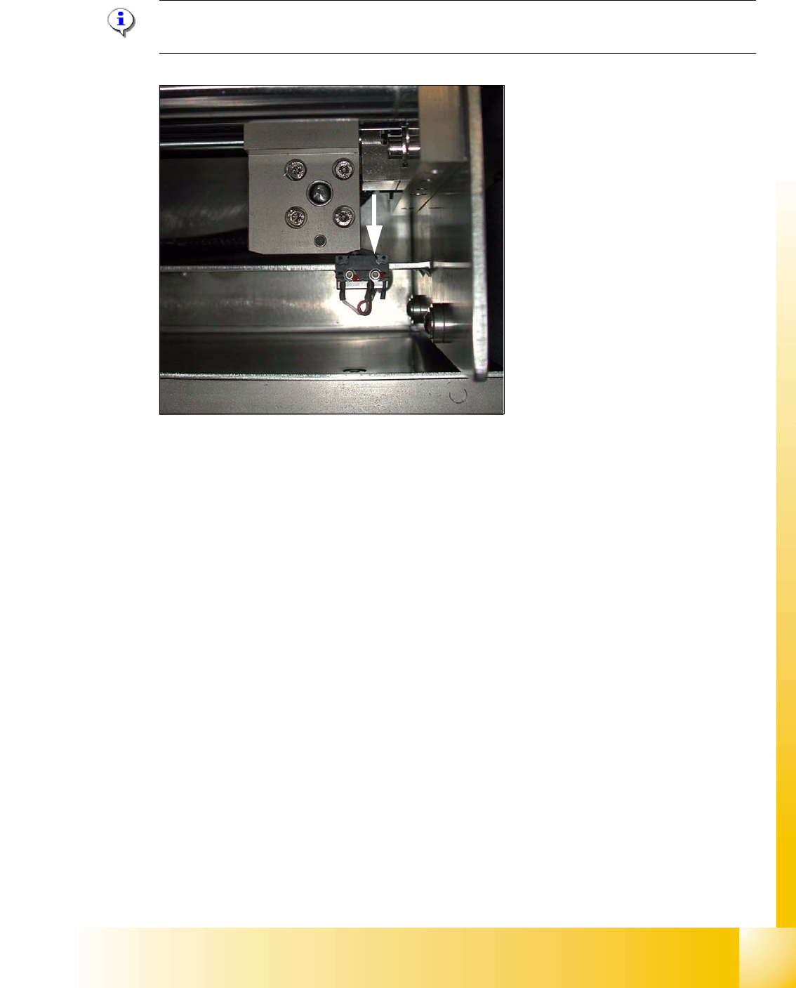
9.2.4.1 Adjusting the limit switch for initialize the driver
Please Note: This is only necessary in case of replacement of the switch or other mal functions
in width adjustment reference run.
Fig. 9.2 - 8 Limit /initialize switch
➠ Move the driver for the width adjustment by hand (via the toothed belt) to the conveyor rail.
➠ Loosen both screws of the limit switch (arrow in Fig. 9.2 - 8)
➠ Move the limit switch in the slot towards the driver and make sure, that the limit switch is safely
switched on.
➠ Check the status of the associated LED on the conveyor control (H41 ini TSP 301) .
➠ Fit the limit switch in this position.
➠ Calibrate the conveyor width via the SITEST program.