SG_FSE_SiplaceHF_HF3_00193901-05_eng.pdf - 第524页
1 - 50 S tudent Guide SIPLACE HF/HF3 1 1 MTC 2 Edition 09/2005 50 Checking and setting the belt tensio n 11 Fig. 1 1.3 - 15 Setting the belt ten sion Key 1 Servo motor of the lif ting axis (shown here for tower 2) 2 Dual…

1 - 49
Student Guide SIPLACE HF/HF3
Edition 09/2005 11 MTC 2
49
➠ Remove the left cover in front of the electronics board and the covers on the right and the left
in front of the Masterdrives.
➠ Switch the motor protection switch off (see Fig. 11.3 - 14).
➠ To relieve the tension the toothed belts, loosen the brake on the servo motor in the following
way to rest the lifting axis on the buffer:
➠ Check that the MTC 2 has been switched off and is isolated from the power supply.
➠ Remove the connector for external signals from the Masterdrive for the lifting axis (see Fig.
11.3 - 14
, item 2).
➠ Move the cable from Pin 3 to Pin 1.
➠ Attach the connector.
➠ Connect the MTC 2 to the power supply and switch it on.
The lifting axis audibly moves a distance of a few mm up to the buffer.
➠ Check that the lifting axis is actually at its end position.
➠ Reconnect the cable as it was originally in the following way:
➠ Switch off the MTC 2 and isolate it from the power supply.
➠ Remove the connector for external signals from the Masterdrive for the lifting axis (see Fig.
11.3 - 14
, item 2).
➠ Move the cable from Pin 1 to Pin 3.
➠ Attach the connector.
➠ Switch the motor protection switch on.
➠ Attach the covers.
➠ Undock the MTC 2 from the SIPLACE station (see User Manual).
➠ Crank up the MTC 2 in a clockwise direction until it stops.
1 - 50
Student Guide SIPLACE HF/HF3
11 MTC 2 Edition 09/2005
50
Checking and setting the belt tension 11
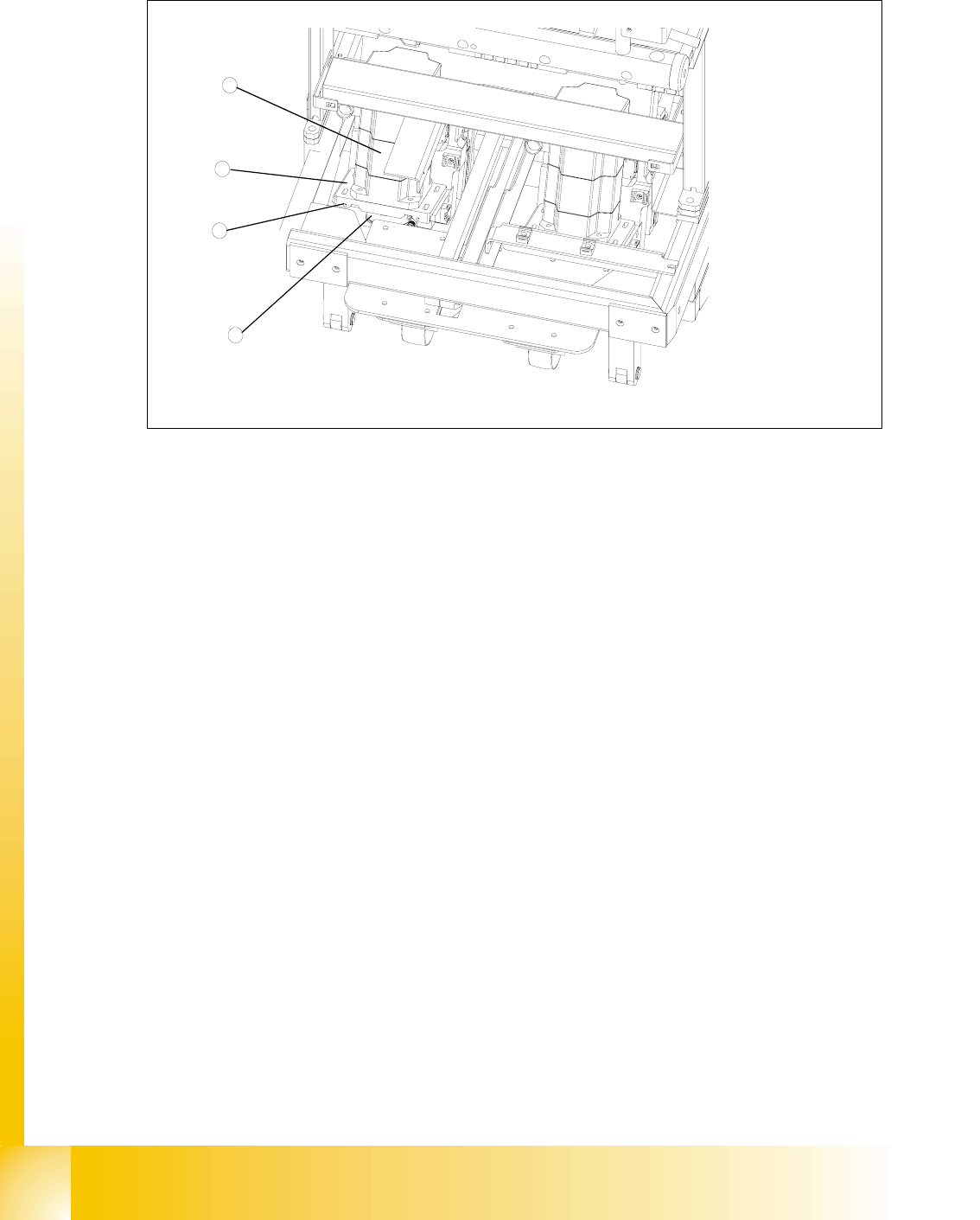
Fig. 11.3 - 15 Setting the belt tension
Key
1 Servo motor of the lifting axis (shown here for tower 2)
2 Dual toothed belt (shown here for tower 2)
3 Mounting plate with clamping screws (shown here for tower 2)
4 Adjusting screws with lock nuts (shown here for tower 2)
➠ Carry out the relevant preparatory measures (see section 11.3.3.1 "Preparatory measures").
➠ Measure the belt tension with the belt frequency measuring device in the following way:
➠ Find the holes for the measurement head of the belt frequency measuring device on the
lifting axis. Two holes are provided for each of the dual toothed belts (see
Fig. 11.3 - 13,
item 7).
➠ Attach the toothed belt tension stickers (Siemens item no. 00370691-0) onto the belts in this
area.
➠ Cause the belts to oscillate and measure their frequency.
You must set the belt tension if the measured frequency deviation deviates from the
nominal value
[(200Hz ± 5Hz),(210Hz ± 5Hz) see note above]
➠ Turn the adjusting screws as far as they will go. Before doing this you will need to loosen
the lock nuts.
➠ Loosen the four lock screws on the mounting plate of the motor.
➠ Use the two adjusting screws to raise the belt tension (by turning in a clockwise direction)
or lower it (by turning in an anticlockwise direction), until the nominal frequency is achieved.
Tighten the lock nuts each time you measure the belt tension.
1
3
4
2
1 - 51
Student Guide SIPLACE HF/HF3
Edition 09/2005 11 MTC 2
51
➠ Firmly tighten the clamping screws and varnish them with red screw locking varnish.
➠ Check the belt tension again.
➠ Remove the belt tension stickers.
➠ Dock the MTC 2 onto the SIPLACE station (see the User Manual).
➠ Check the zero offset of the lifting axis if you have changed the belt tension.
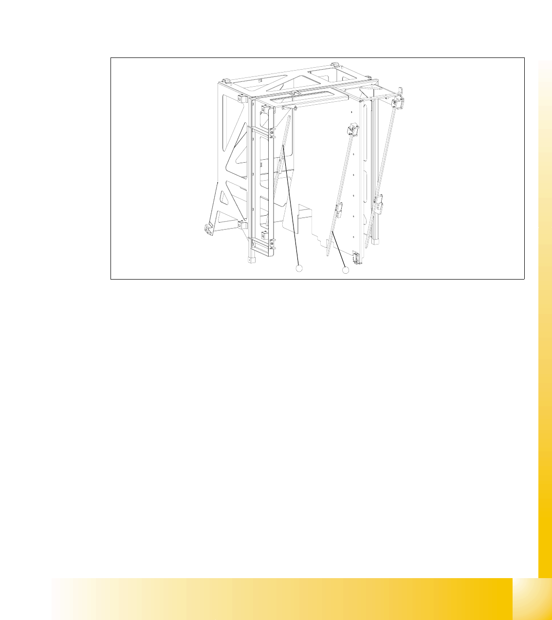
11.3.3.2 Guide rails and stopper bars
Fig. 11.3 - 16 Guide rails and stopper bars in the upper frame
Key
1 Guide rail (shown here for tower 1)
2 Stopper bar (shown here for tower 1)
Tools and accessories 11
– 1 set of hexagon socket wrenches
Preparatory measures 11
➠ Move the lifting axis into the refill position for cassette 1 and completely set up the MTC 2 with
empty cassettes (see User Manual).
➠ Set up every cassette with an empty WTC in the bottom and in the top level.
2
1