SG_FSE_SiplaceHF_HF3_00193901-05_eng.pdf - 第259页
1 - 59 S tudent Guide SIPLACE HF/HF3 Edition 09/2005 6 Colle ct &Place-Head / DLM2 59 Plug X2, 40-pin 6 Connected to plug X13 on the head bo ard 6 – V olta ge supply and track signals for the st ar-axis drive – Refer…
1 - 58
Student Guide SIPLACE HF/HF3
6 Collect &Place-Head / DLM2 Edition 09/2005
58
6
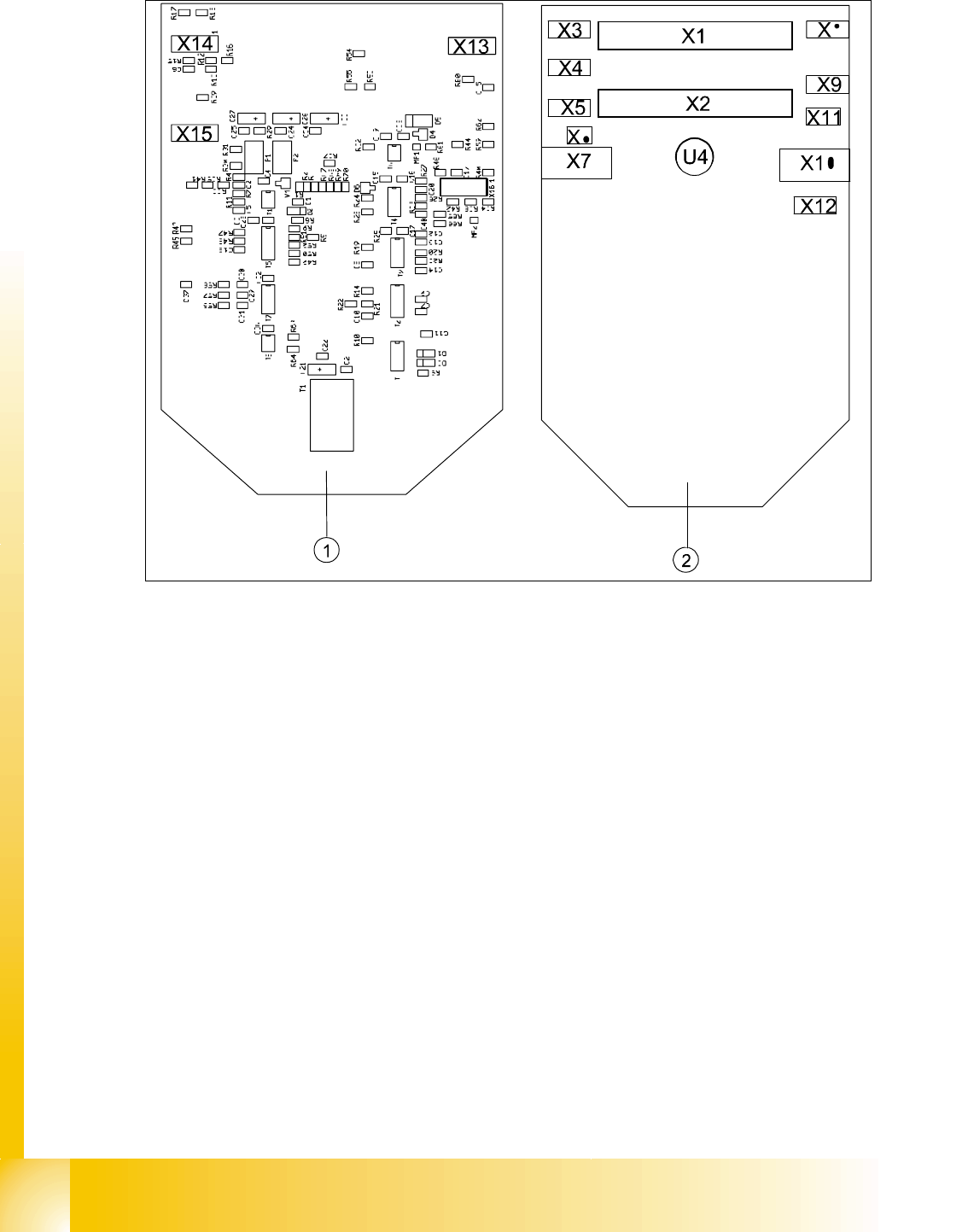
Abb. 6.4 - 9 Intermediate distributor - position of the sockets
Legende
The following supply voltages and signals are routed by the intermediate distribution board to the
individual placement head modules or to the head board:
6
Plug X1, 40-pin 6
Connected to plug X14 on the head board 6
– Voltage supply, tacho and track signals for the Z-axis drive
– Signal from light barrier "Z-axis in top position"
– Signal from light barrier "Z-axis in bottom position" (sensor stop signal)
– Control signal for the forced air valve
– Supply voltage + 5VDC, ± 15VDC
– Reference point signal for the DP-axis
– Track signals for the DP-axis
(1) Front of the intermediate distributor (2) Back of the intermediate distributor
U4 Pressure sensor for air kiss
X16

1 - 59
Student Guide SIPLACE HF/HF3
Edition 09/2005 6 Collect &Place-Head / DLM2
59
Plug X2, 40-pin 6
Connected to plug X13 on the head board 6
– Voltage supply and track signals for the star-axis drive
– Reference point for the star-axis
– Analog forced air pressure value
– Supply voltages + 5VDC, ± 15VDC, + 24VDC
Plug X3, 10-pin 6
Connection for the Z-motor and Z-tacho signal (Tacho signal is not use on the HF-machine) 6
Plug X4, 10-pin 6
Connection for the Z-axis track signals 6
Plug X5, 10-pin 6
Connection for the star motor 6
Plug X6, 6-pin 6
Connection for the forced air valve 6
Plug X7, 10-pin 6
Connection for the DP-axis track signals 6
Plug X10, 10-pin 6
Connection for the "Z-axis up" signal 6
Plug X11, 8-pin 6
Connection for the light barrier "Z-axis down" signal (sensor stop signal) 6
Plug X12, 10-pin 6
Connection for the star-axis track signals 6
Plug X13, 10-pin 6
Test connection for the Z-axis track signals
Plug X14, 10-pin 6
not used
Plug X15, 10-pin 6
Test connection for the Star-axis track signals
Plug X15, 10-pin 6
Test connection for the Dp-axis track signals
1 - 60
Student Guide SIPLACE HF/HF3
6 Collect &Place-Head / DLM2 Edition 09/2005
60
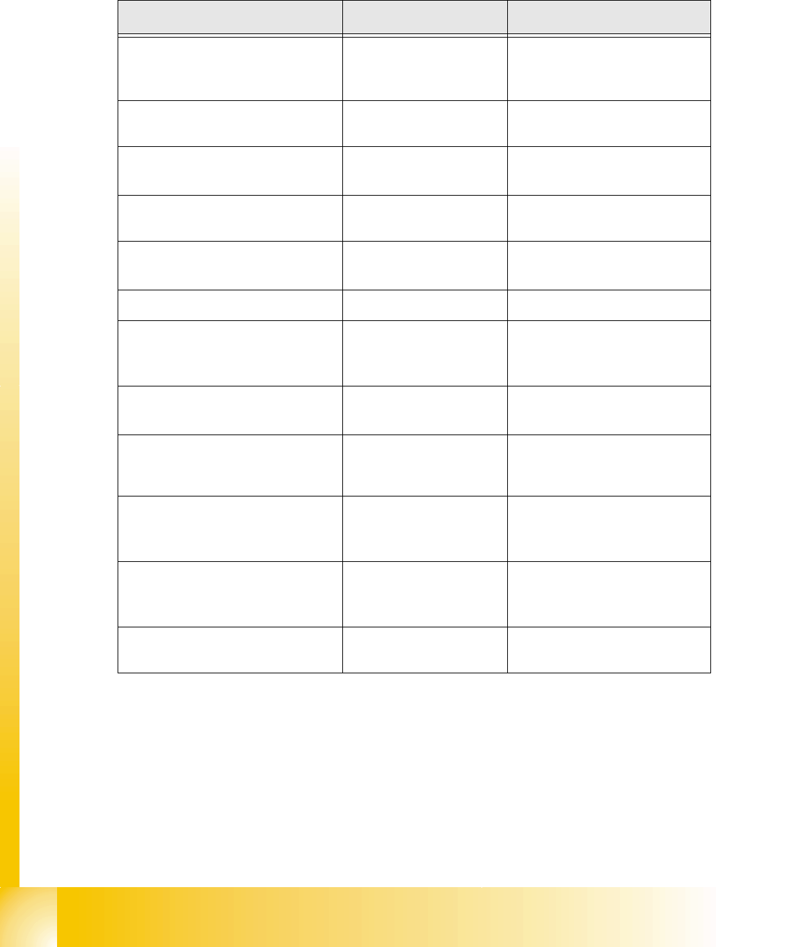
6.4.2 Overview Adjustments on the DLM 2 C&P head
Description Tools &Equipment Adjustments
Mounting the star onto the motor shaft
of the star motor
Adjustment with the Po-
wer pack and the gauge
for the star
Check the magnetic neutral
position with the Sitest
(max.Deviation 95 Digit)
Determine zero point correction for the
star
Gauge for zero point cor-
rection / Sitest
Write the determine value in the
Sitest under position
Switch setting on the DLM 2 (Resolu-
tion track signals 10-25) nothing
Switch setting on HF machine
to 25
DP-axis Incremental encoder adjust-
ment to the glass scale (segment) Parallel pin 1,4 - 1,6 mm
Distance 1,5 mm
Adjustment mechanical position of
valve drives
Distance gauge
0,2 mm
0,2 mm Distance plunger to the
valve frame
Light barrier bottom position Z-axis Parallel pin 1,0 mm Distance 1,0 mm
Clamping device on Z-belt
Clamping device have to lay in
the top and bottom position on
the teeth
Belt tension of the Z-axis
Belt tension measure-
ment device
Belt tension
280 +/- 5 Hz
Setting the stop for the Z-axis
Gauge for the Z-mechani-
cal end stop
(03019865-01)
Correct position are necessary to
determine the zero point correc-
tion Z-axis.
Mechanical adjustments Air kiss tubes
on the star
Check with your eyes
Check the distance between
incremental encoder dp and air
kiss tubes.
Adjustments tube for air kiss supply
feeler gauge
Air kiss tubes should be ap-
prox. 0,7 mm over the frame of
the circular guide
Adjustments air pressure values
Compressed air testing de-
vice 150 mbar on open 9x4 nozzle
Table 6.4 - 1 Adjustments on the DLM 2 C&P head