SG_FSE_SiplaceHF_HF3_00193901-05_eng.pdf - 第96页
1 - 26 S tudent Guide SIPLACE HF/HF3 3 Communication and Control Edition 09/2005 26 connector X5rb (input) nozzle chan ger 1 and 4 3 connector X7rb (output) 3 connector X8rb (output) 3 X5rb Input Pin 1 M_nozzle left (ope…
1 - 25
Student Guide SIPLACE HF/HF3
Edition 09/2005 3 Communication and Control
25
connector X8qb (output) 3
3.3.9.3 CAN I/O in sub-distributor section 4
connector X3rb (input) 3
connector X4rb (input) 3
X8qb Output
Pin 1 nozzle changer 2, valve A D8
Pin 2 nozzle changer 2, valve B D9
Pin 3 nozzle changer 3, valve A D10
Pin 4 nozzle changer 3, valve B D11
Pin 5 green indicator D12
Pin 6 indicator 1 D13
Pin 7 indicator 2 D14
Pin 8 indicator 3 D15
X3rb Input
Pin 1 Emergency stop loop o.k. D0
Pin 2 M_Servo Address bus D1
Pin 3 M_Servo Address bus D2
Pin 4 M_Servo Address bus D3
Pin 5 M_Servo Address bus D4
Pin 6 M_pressure main valve 2 D5
Pin 7 not used D6
Pin 8 not used D7
X4rb Input
Pin 1 M_start button D8
Pin 2 M_stop button D9
Pin 3 not used D10
Pin 4 M_gantry crash gantry 2 D11
Pin 5 M_temperature to high 2 D12
Pin 6 M_control On 1 D13
Pin 7 M_temperature to high 3 D14
Pin 8 not used 3 D15
1 - 26
Student Guide SIPLACE HF/HF3
3 Communication and Control Edition 09/2005
26
connector X5rb (input) nozzle changer 1 and 4 3
connector X7rb (output) 3
connector X8rb (output) 3
X5rb Input
Pin 1 M_nozzle left (open) A D16
Pin 2 M_nozzl right (closed) A D17
Pin 3 M_nozzle left (open) B D18
Pin 4 M_nozzle right (closed) B D19
Pin 5 M_nozzle left (open) A D20
Pin 6 M_nozzle right (closed) A 1 D21
Pin 7 M_nozzle left (open) B D22
Pin 8 M_nozzle right (closed) B 3 D23
X7rb Output
Pin 1 Ctrl_Servo Slot D0
Pin 2 Ctrl_Servo Slot D1
Pin 3 Ctrl_Servo Slot D2
Pin 4 Ctrl_Servo Slot D3
Pin 5 Ctrl_Servo Slot D4
Pin 6 Ctrl_pressure main valve D5
Pin 7 trigger LP2 D6
Pin 8 trigger Be2 D7
X8rb Output
Pin 1 nozzle changer 1, valve A D8
Pin 2 nozzle changer 1, valve B D9
Pin 3 nozzle changer 4, valve A D10
Pin 4 nozzle changer 4, valve B D11
Pin 5 not used D12
Pin 6 not used D13
Pin 7 not used D14
Pin 8 not used D15
1 - 27
Student Guide SIPLACE HF/HF3
Edition 09/2005 3 Communication and Control
27
3.3.10 CAN I/O Module (SLIO) HF from MA.No. xx
Two CAN Bus I/O modules are integrated in the different section of the HF machine. Both modules
are fully identical
Product characteristics:
– micro controller with integrated CAN controller
– data memory
– programm memory (flash)
– CAN interface with 9 pin connector and address alignment
– 16 digital Output 24 V with status LED
– 24 digital Input 24 V with status LED
– download interface
– power supply 5 V and 24 V
– extended Board on the I/O Module for "One Wire Bus"
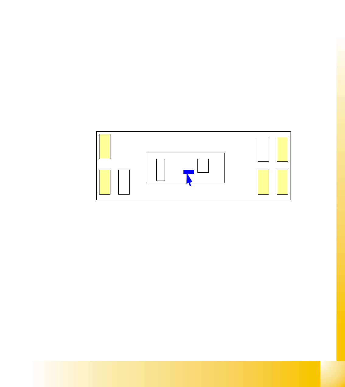
Fig. 3.3 - 21 overview CAN I/O module
Legend
(1) DIP switches ONE Wire board have Paßtrough connectors for
CAN-Bus and RS 232.
X1 CAN-Interface on "ONE Wire Board" RS232 analog interface, bootstraploader inter-
face
X3, X4, X5 digital inputs 24V X6 power supply 5V
X7, X8 digital outputs 24V X9 power supply 24V
X
7
X
1
R
S
2
3
2
X3, X4, X5 digital input
X7, X8 digital output
CAN I/O module
X
8
X
9
X
3
X
4
X
6
X
5
One Wire
Board
(1)