SG_FSE_SiplaceHF_HF3_00193901-05_eng.pdf - 第45页
1 - 19 S tudent Guide SIPLACE HF/HF3 Edition 09/2005 2 Overview 19 2.2.7.2 Axis Unit Placement Are a 2 HF3 machine The axis unit in the placement area 2 is prepared also for two gantrys, for a futu re machine gen- eratio…
1 - 18
Student Guide SIPLACE HF/HF3
2 Overview Edition 09/2005
18
2.2.7 Axis Units HF3 machine
The flexible axis unit will be equipt with servo boards depends the machine configuration.
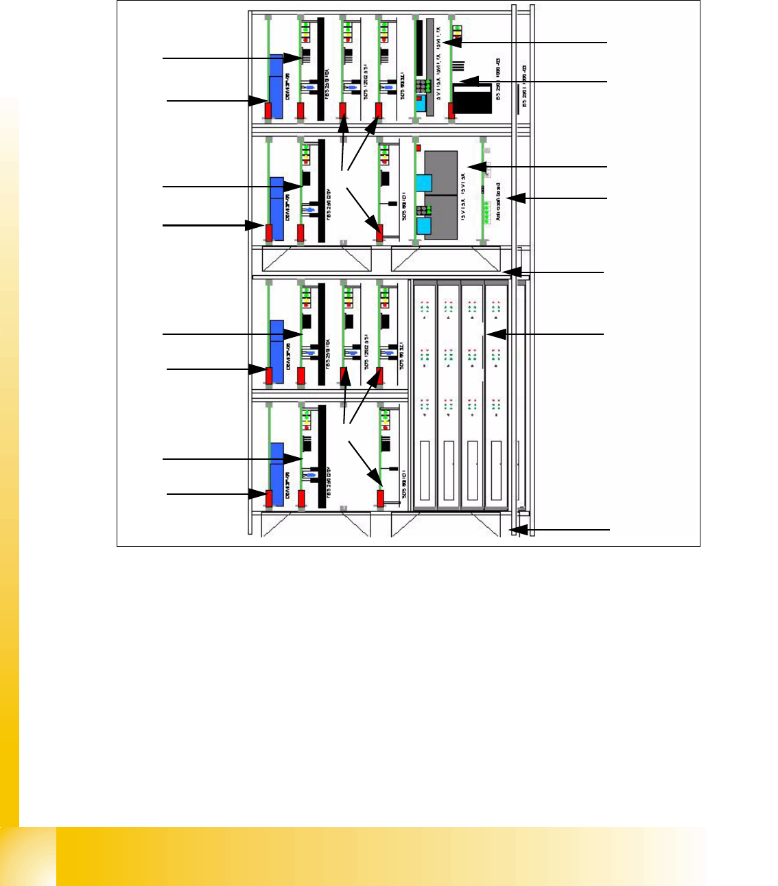
2.2.7.1 Axis Unit Placement Area 1 HF3 machine
Fig. 2.2 - 9 Axis unit PA1 at HF 3
Legend
(1) DC/DC converter 5V/15A for Axis unit (2)
Ballast circuit board
(3) DC/DC converter +/-15V for gantries and
head interface, 5V CAN BUS
(4) Anti crash board
(5) Fan unit (blow downwards) (6) Axis boards
(7)
Servo boards X-Axis Placement area 1 for gan-
tries 1/4
(8) Servo boards Y-Axis Placement area 1 for gan-
tries 1/4
(9) Brake board for each X and Y Axes (10) Servo boards Star-/Z-/DP-Axes gantries 1/4
1
2
3
4
5
6
7
9
8
9
7
9
8
9
Placement area 1
Gantry 1
Placement area 1
Gantry 4
5
10
10
1 - 19
Student Guide SIPLACE HF/HF3
Edition 09/2005 2 Overview
19
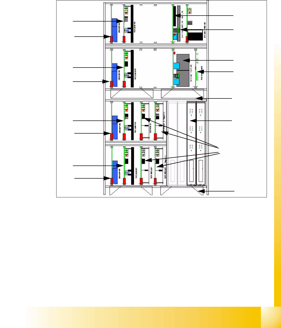
2.2.7.2 Axis Unit Placement Area 2 HF3 machine
The axis unit in the placement area 2 is prepared also for two gantrys, for a future machine gen-
eration with 4 gantrys.
Fig. 2.2 - 10 Axis unit PA2
Legend
(1) DC/DC converter 5V/15A for Axis unit (2)
Ballast circuit board
(3) DC/DC converter +/-15V for gantrys and
headinterface, 5V CAN BUS
(4) Anti crash board
(5) Fan unit (blow downwards) (6) Axis boards
(7)
Servo boards X-Axis Placement area 2 for gan-
try (2/)3
(8) Servo boards Y-Axis Placement area 2 for
gantry (2/)3
(9) Brake board for each X and Y Axes (10) Servo boards Z/D-Axes Placement area 2 for
TWIN head3
1
2
3
4
5
6
7
9
8
9
7
9
8
9
Placement area 2
Gantry 2 not used
Placement area 2
Gantry 3
5
10
1 - 20
Student Guide SIPLACE HF/HF3
2 Overview Edition 09/2005
20
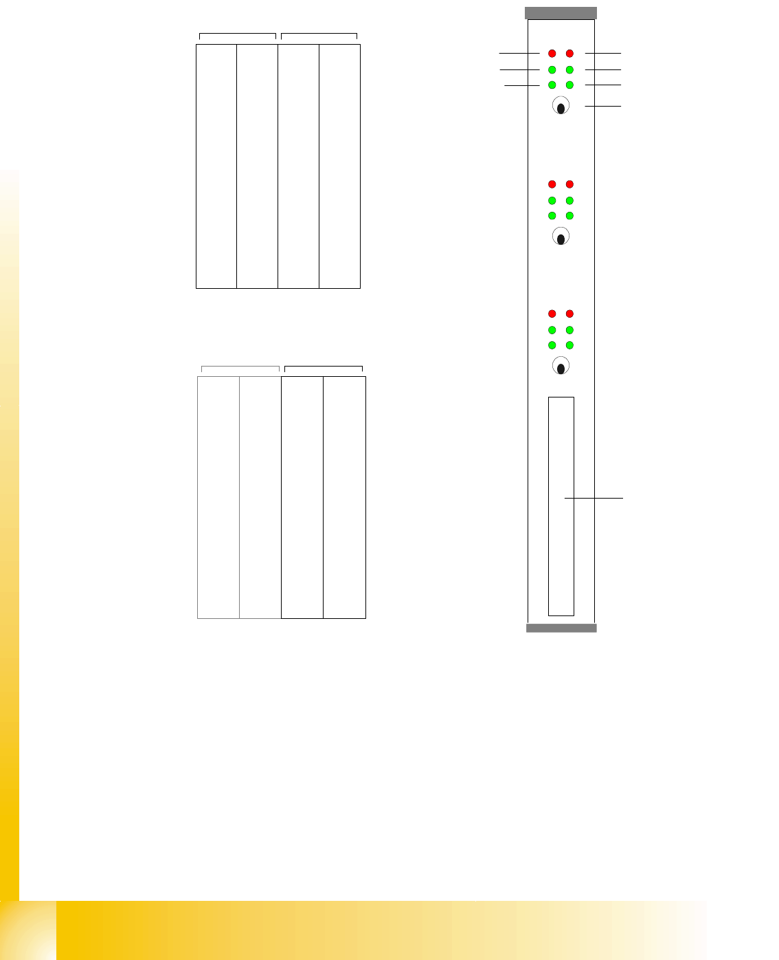
2.2.7.3 Axis Card A363
Abbreviation:
X = X-Axis and Gantry number
Z1=Z-Axis for Twin head Modul 1
Y= Y-Axis and Gantry number D
1=turning Axis for Twin head Modul 1
S= Star Axis and Gantry number for C&P head Z
2=Z-Axis for Twin head Modul 2
Z= Z-Axis and Gantry number for C&P head D
2=turning Axis for Twin head Modul 2
DP= Swivel Axis and Gantry number for C&P
head
Counter error
Zero puls
End signal
Common error,
Board error
Initialisation
Servo On
Axis switch off/on
Axis 0
Axis 1
Axis 2
Interface
Axis test box
X 1
Address
0
Y 1
Address
1
S 1
Address
2
Z 1
Address
3
DP 1
Address
5
free
Address
5
X 4
Address
6
Y 4
Address
7
S 4
Address
8
Z 4
Adress
9
DP 4
Address
10
free
Address
11
Gantry 1 Gantry 4
Placement area PA 1
Servos 'bottom'Servos 'top'
X 2
Address
16
Y 2
Address
17
S 2
Address
18
Z 2
Address
19
DP 2
Address
20
free
Address
21
X 3
Address
22
Y 3
Address
23
S3/Z
2
Address
24
Z/Z
1
Address
25
DP/D
1
Address
26
/D
2
Addres
27
Gantry 2 not used Gantry 3
Placement area PA 2
Servos 'bottom'Servos 'top'