SG_FSE_SiplaceHF_HF3_00193901-05_eng.pdf - 第261页
1 - 61 S tudent Guide SIPLACE HF/HF3 Edition 09/2005 6 Colle ct &Place-Head / DLM2 61 6.4.3 Removal of st ar 6.4.3.1 T ools and equipment – Set of DIN 91 1 Allen keys – Gauge for the star (C&P head / DLM1/2), art…

1 - 60
Student Guide SIPLACE HF/HF3
6 Collect &Place-Head / DLM2 Edition 09/2005
60
6.4.2 Overview Adjustments on the DLM 2 C&P head
Description Tools &Equipment Adjustments
Mounting the star onto the motor shaft
of the star motor
Adjustment with the Po-
wer pack and the gauge
for the star
Check the magnetic neutral
position with the Sitest
(max.Deviation 95 Digit)
Determine zero point correction for the
star
Gauge for zero point cor-
rection / Sitest
Write the determine value in the
Sitest under position
Switch setting on the DLM 2 (Resolu-
tion track signals 10-25) nothing
Switch setting on HF machine
to 25
DP-axis Incremental encoder adjust-
ment to the glass scale (segment) Parallel pin 1,4 - 1,6 mm
Distance 1,5 mm
Adjustment mechanical position of
valve drives
Distance gauge
0,2 mm
0,2 mm Distance plunger to the
valve frame
Light barrier bottom position Z-axis Parallel pin 1,0 mm Distance 1,0 mm
Clamping device on Z-belt
Clamping device have to lay in
the top and bottom position on
the teeth
Belt tension of the Z-axis
Belt tension measure-
ment device
Belt tension
280 +/- 5 Hz
Setting the stop for the Z-axis
Gauge for the Z-mechani-
cal end stop
(03019865-01)
Correct position are necessary to
determine the zero point correc-
tion Z-axis.
Mechanical adjustments Air kiss tubes
on the star
Check with your eyes
Check the distance between
incremental encoder dp and air
kiss tubes.
Adjustments tube for air kiss supply
feeler gauge
Air kiss tubes should be ap-
prox. 0,7 mm over the frame of
the circular guide
Adjustments air pressure values
Compressed air testing de-
vice 150 mbar on open 9x4 nozzle
Table 6.4 - 1 Adjustments on the DLM 2 C&P head
1 - 61
Student Guide SIPLACE HF/HF3
Edition 09/2005 6 Collect &Place-Head / DLM2
61
6.4.3 Removal of star
6.4.3.1 Tools and equipment
– Set of DIN 911 Allen keys
– Gauge for the star (C&P head / DLM1/2), article number 00326164-01
– 5V Power supply for the C&P head / DLM1/2, article number 00353277-01
6.4.3.2 Dismantling the placement star
➠ Dismantle the front part of the C&P head.
➠ Place the front part of the revolver head on the tray.
➠ Remove all the sleeves (item 1 in Fig. 6.4 - 10) and place them in the sleeve boxes or on a soft,
clean surface.
➠ Loosen the three M3x8 hexagon socket head screws (item 5 in Fig. 6.4 - 10).
➠ Raise the star slightly.
➠ Lift the placement star up with a careful rotation and off.
6
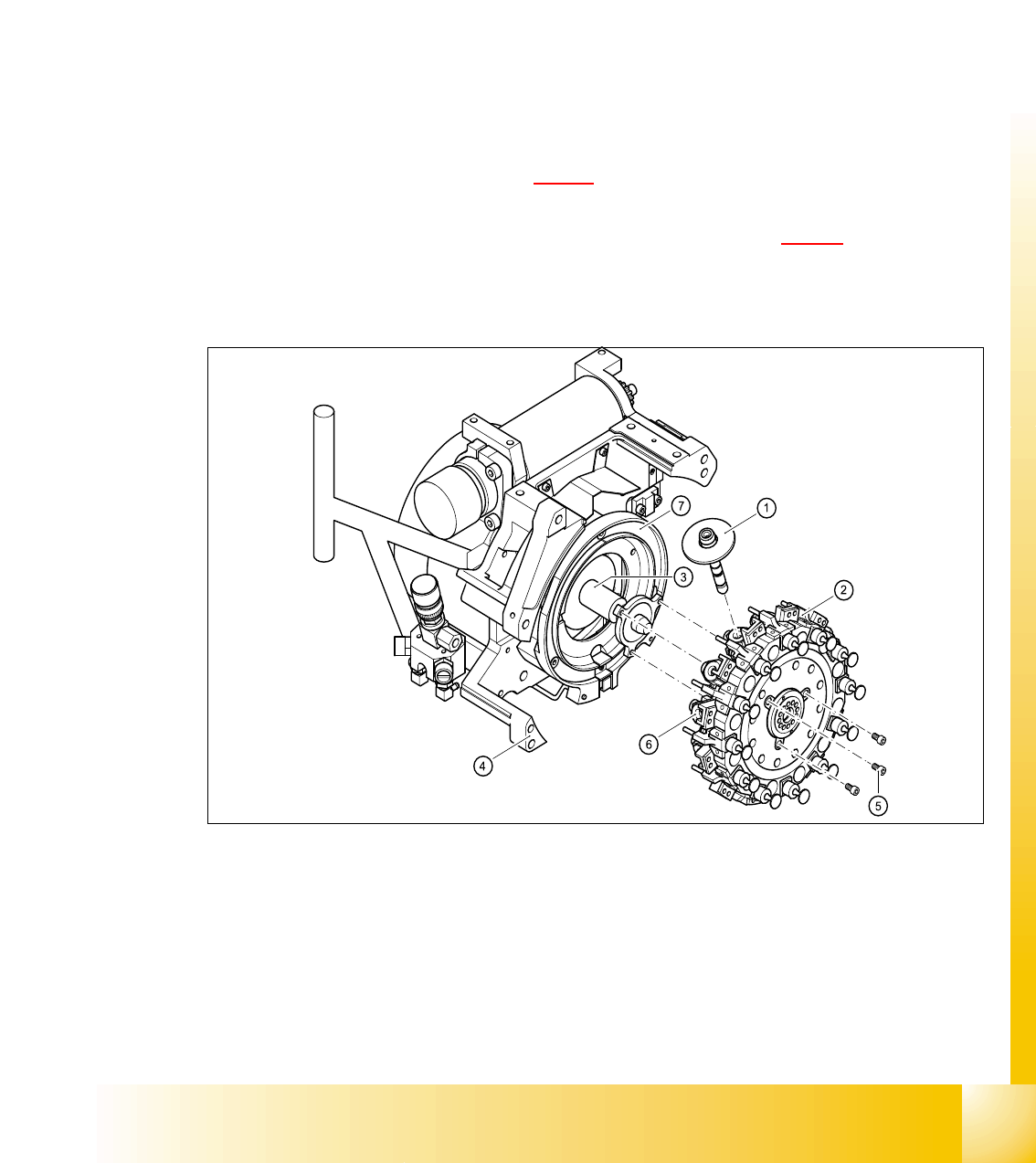
Fig. 6.4 - 10 Removal of star (Picture DLM 1)
Legend
(1) Sleeve (2) Star, mounted / DLM2
(3) Star drive (4) Front part of revolver head
(5) M3x8 hexagon socket head screws, 3x (6) Segment
(7) Raceway (Circular guide)

1 - 62
Student Guide SIPLACE HF/HF3
6 Collect &Place-Head / DLM2 Edition 09/2005
62
6.4.3.3 Fitting the star
Please Note:
Remove any remaining sleeves before fitting the star.
Push all the segments (item. 6 in Fig. 6.4 - 10
) slightly outwards.
➠ Insert small Allen keys (e.g. size 2) into the holes for the star fixing screws (item 5 in Fig.
6.4 - 10
).
➠ Hold the star over the star drive shaft (item 3 in Fig. 6.4 - 10) so that the Allen keys slide into
the threaded holes in the star drive.
➠ Push all the segments outwards.
➠ Insert the star.
Please Note:
Make sure that the vacuum hoses of the segments do not become squashed.
➠ Push all the segments inwards so that the segment ball bearings slide into the raceway (item
7 in Fig. 6.4 - 10
).
➠ Check that the star is seated flat on the drive shaft.
➠ Loosely tighten the three M3x8 hexagon socket head screws on the star so that the screws can
still move slightly in the fixing holes.
6.4.3.4 Adjusting the star with respect to the star's magnetic neutral position.
The aim of adjusting the star is to ensure that the vertical axis of segment no. 1 is aligned with the
magnetic neutral position of the star step motor.
6
➠ To do this, insert the gauge pin into the gauge for the star and into the hole in the segment
no. 1, until it reaches the stop.
➠ Pull off the motor line plug of the star motor from socket X5 on the intermediate distribution
board and connect the motor line to the power supply.
➠ Connect the power supply unit to main power.
➠ Tighten the three M3x8 hexagon socket head screws on the star.
➠ Remove the gauge pin.
➠ Insert the gauge pin again into the gauge for the star and into the hole in the segment, until it
reaches the stop. Then check:
– that the gauge pin can be inserted easily.
➠ Disconnect the power pack from the power source.
➠ Insert the gauge pin again into the gauge for the star and into the hole in the segment, until it
reaches the stop. Then check:
– that the star does not rotate out of its current position as a result.
If both of these conditions are fulfilled, then the star has been fitted correctly.
6