SG_FSE_SiplaceHF_HF3_00193901-05_eng.pdf - 第290页
1 - 90 S tudent Guide SIPLACE HF/HF3 6 Collect &Place-He ad / DLM2 Edition 09/2005 90 12 segment C&P head DLM2 - signal for Z-axis 6 Fig. 6.6 - 12 Dynamic signals Z- axis into free space for 12 segment C&P-he…
1 - 89
Student Guide SIPLACE HF/HF3
Edition 09/2005 6 Collect &Place-Head / DLM2
89
– Move the gantry in the Service position, so that the Z-axis move in a free space.
SITEST: 6
➠ "Select "C&P heads" ==> "Select head" ==>"Axis functions" ==> "Select
Z-axis" ==> "Continuous run Z-axis" ==> "Select DIGIT for display" ==>"Edit: Target position
685 digits and Position mode = absolut" ==> "Sart".
➠ If necessary, press the START button.
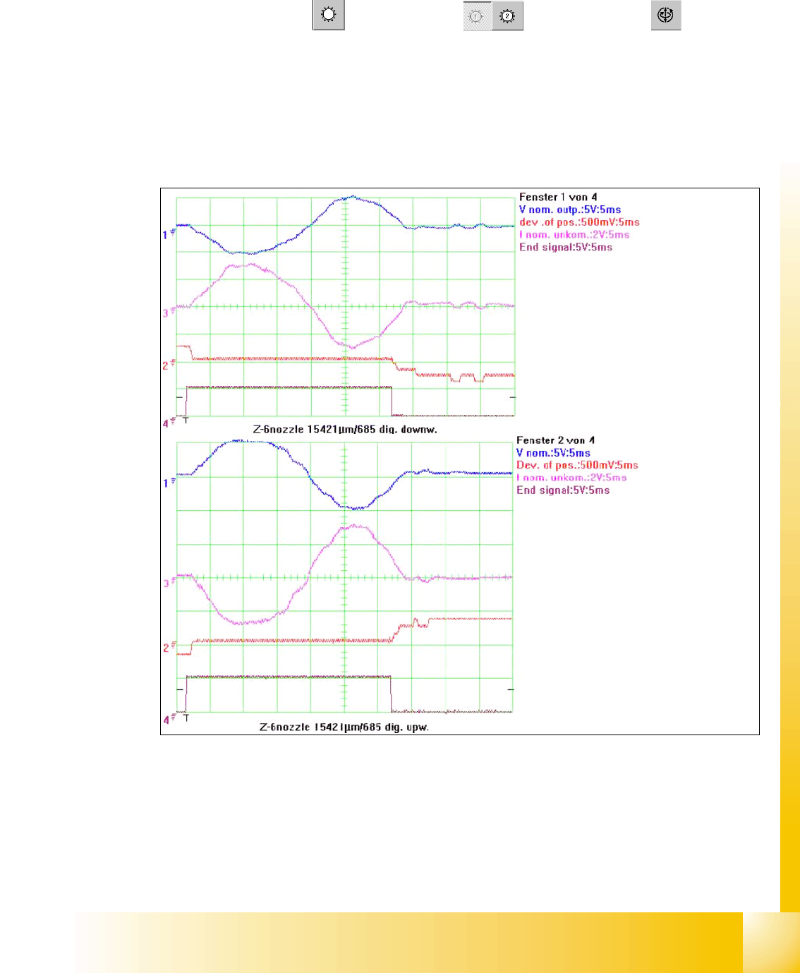
6.6.4.3 Example for dynamic with the control signal of the Vnom. output
Fig. 6.6 - 11 Dynamic signals Z-Axis for excample 6 segment C&P head
Legend
(1) Control signal (Axis testbox V nom.) (2) Uncommutated Current signal Axis adap-
ter
(3) Position of deviation (4) End signal
1
2
3
4
1
2
3
4
1 - 90
Student Guide SIPLACE HF/HF3
6 Collect &Place-Head / DLM2 Edition 09/2005
90
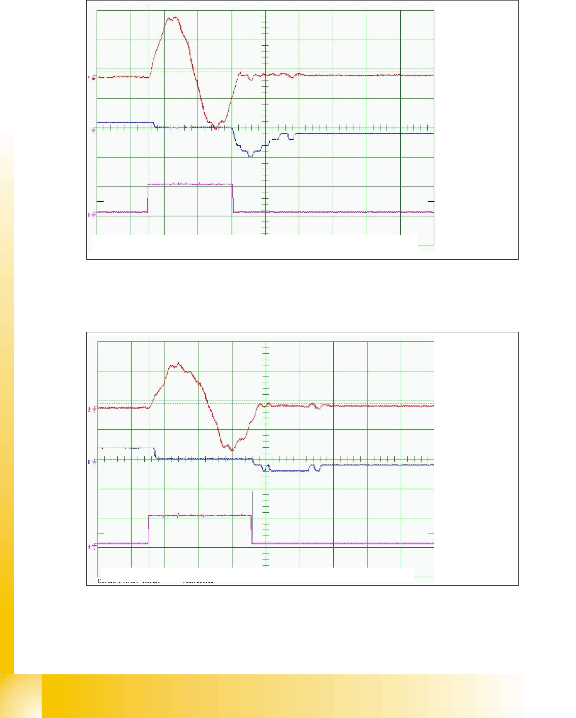
12 segment C&P head DLM2 - signal for Z-axis
6
Fig. 6.6 - 12 Dynamic signals Z- axis into free space for 12 segment C&P-head DLM2
6
6 segment C&P head DLM2 - signal for Z-axis 6
6
Fig. 6.6 - 13 Dynamic signals Z-axis into free space for 6 segment C&P-head DLM2
Positioning time: 24ms - 1ms Distance 685 digits
Current nominal
Deviation of pos.
End signal
10ms/Div
2V/Div
500mV/Div
Soll-Positionierzeit: 30ms +/- 3ms Distance 685 digits
Current nominal
Deviation of pos.
End signal
2V/Div
500mV/Div
10ms/Div
1 - 91
Student Guide SIPLACE HF/HF3
Edition 09/2005 6 Collect &Place-Head / DLM2
91
6.6.5 Axis control Dp-Axis
The Dp axis is driven with a DC servo motor. The control of the axis occurred with one control
signals of the VC3 controller I
nom "W" and I nom "U" = 0. The intermediate circuit voltages is
approx. 60V.
Via a stepping motor, the Dp axis is coupled to the segment of the glass scale. The Dp axis posi-
tions the segment into its position, the Dp axis is then decoupled via the stepping motor again.
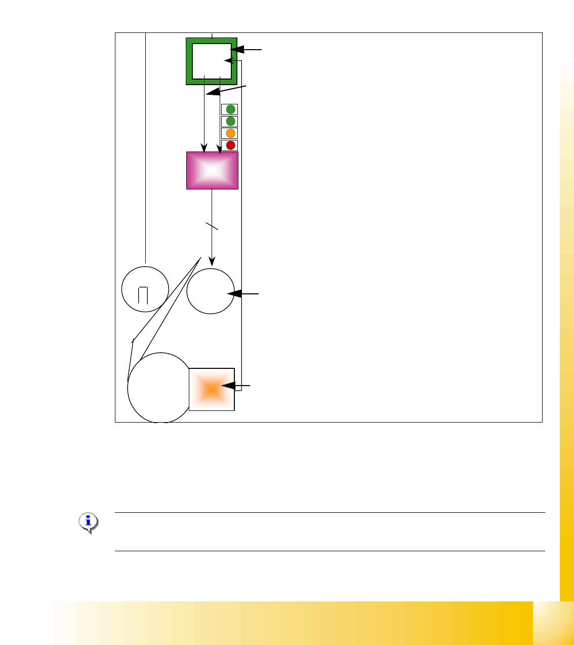
Fig. 6.6 - 14 Axis control DP-Axis
6.6.5.1 Check the dynamic DP-Axis
6.6.5.2 Test setup
Please Note:
The test setup for the DP-Axis is the same as the Star-Axis
VC 3
cont
Servo
ampl.
2
M
M
=
Segment
glass
disc
Enco-
der
Swivel in out
Axis card A363 with VC 3 Controller (VC = Velocity Commutation)
Control signal I
nom "W"
LED‘s on the Servo amplifier:
– Power supply ON
– Servo enable, if the the enable signal from the axis board avai-
lable.
– Display R.M.S. current limiter shorter than 2,5 s.
– Error: Overvoltage, -current, -temperature or Nominal current-
overstepping longer than 2,5 sec.
Servo board control directly the DC motor.
DC motor.
Incremental encoder: transmit the exact position of the axis via
the track signals.