SG_FSE_SiplaceHF_HF3_00193901-05_eng.pdf - 第214页
1 - 14 S tudent Guide SIPLACE HF/HF3 6 Collect &Place-He ad / DLM2 Edition 09/2005 14 6.2.1 Reference run C&P head Fig. 6.2 - 1 General reference run C&P head Press Start Button Initialise all Stepper motors …
1 - 13
Student Guide SIPLACE HF/HF3
Edition 09/2005 6 Collect &Place-Head / DLM2
13
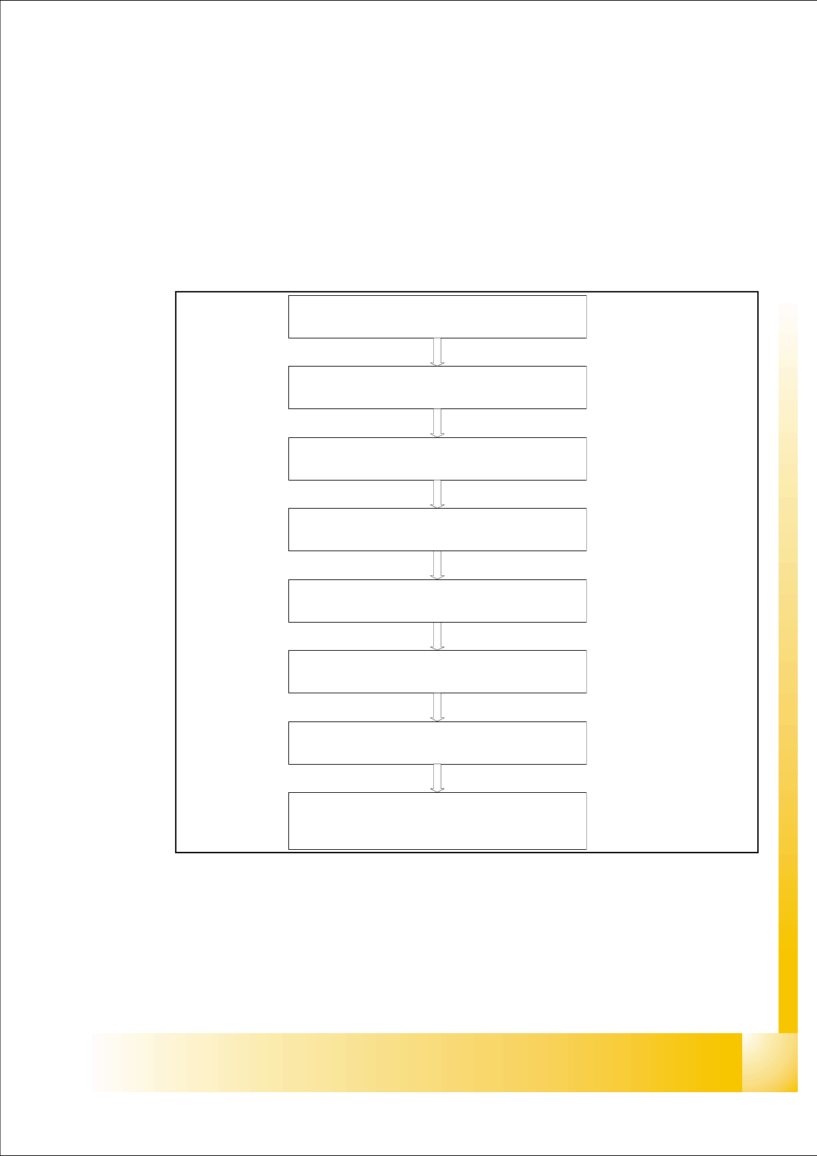
6.2 Reference Run
The 6 and 12 C&P head has 3 axes Star, Z and DP and the X and Y axes for the Gantry. The Twin
head consist of two axes one Z axis for up and down and one D axis for rotation. Before you start
the production you must initialize all axes that the axis controller know their actual mechanical po-
sition.
General sequence 6
– This principle about the reference run is the same at DLM1 or 2 6 - or 12 nozzle C&P head.
– The reference run starts with the initialisation of all the head stepper motors. This allows then,
the head axis to reference by moving first to their zero pulses and then to their zero point cor-
rection values.
– For the Siplace HF machine both heads (C&Phead,Twin head) and gantrys reference at the
same time .
Press Start Button
X / Y Axis reference run
Initialize all head axes (C&P,Twin head)
X/Y Axis move the C&P head ,Twin head to reject
position
Vacuum measurement for all segments
X/Y Axis move C&P, Twin head to fixed transport rail
Nozzle height measurement for all segments
Transport reference run
X/Y Axis move to the waiting position
1 - 14
Student Guide SIPLACE HF/HF3
6 Collect &Place-Head / DLM2 Edition 09/2005
14
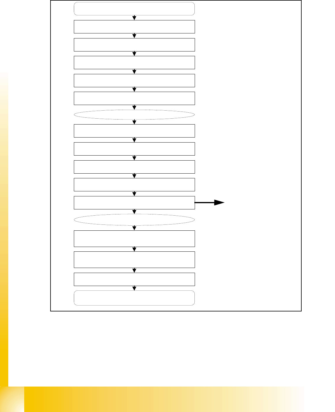
6.2.1 Reference run C&P head
Fig. 6.2 - 1 General reference run C&P head
Press Start Button
Initialise all Stepper motors
Z-Axis pre-reference run
Star-Axis reference run
Z-Axis complete reference run
DP-Axis reference run
Head reference completed
XY-Axis, gantryreference run
XY-Axis move C&P Head to reject bin
sleeves to initial position
Vacuum measurement for all segments
Vacuum reference completed
XY-Axis move C&P Head to fixed
transport rail
Nozzle height measurement
for all segments
Transport reference run
XY axis move to waiting position
Nozzle lenght measurement for nozzles
OPTION
Option:Component Sensor
1 - 15
Student Guide SIPLACE HF/HF3
Edition 09/2005 6 Collect &Place-Head / DLM2
15
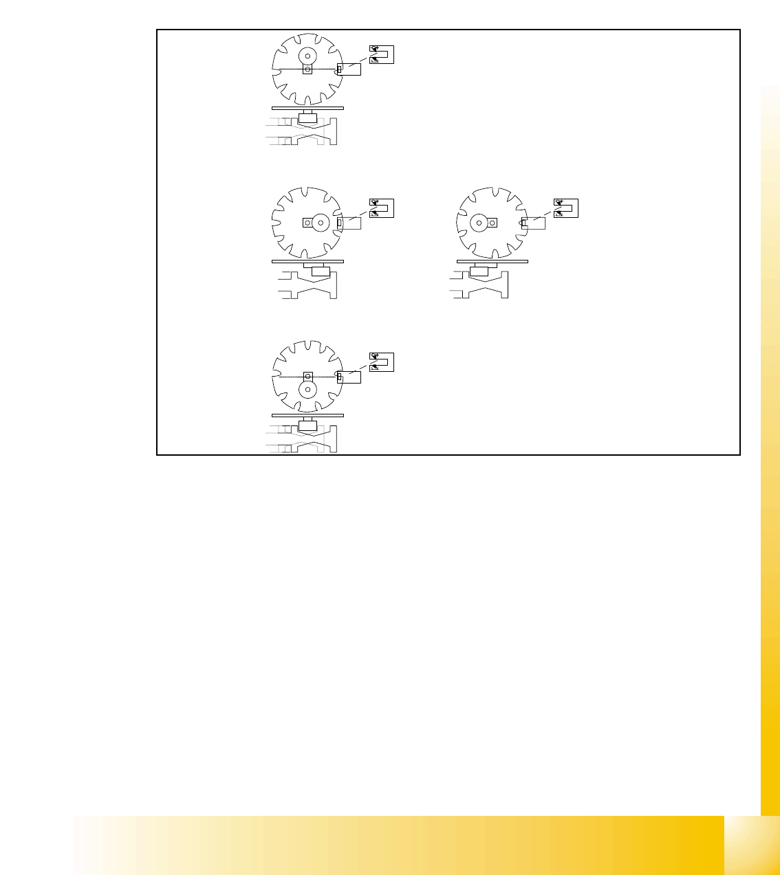
6.2.2 Initialize Valve Drive at Pick-up / Placement Position / Reject Position
The function of the stepper motor, with the aid of an eccentric movement, is to move the plunger
which will switch vacuum on and allow component to be picked. When placing the component the
plunger is switch again for nozzle closed, so that we have air kiss on the nozzle for placement.
When reject the component the plunger will switch air kiss on and allow component to be rejected.
After this we switch back on vacuum .
Fig. 6.2 - 2 Initialize valve drive at pick-up / placement / reject position
Key:
(3) Home position, initial position. Give way free for Star axis movement. Drawing show 2 possible
positions of the plunger
(4) 2a. is switching to vacuum, Vacuum value "Nozzle open"
2b. is switching to air kiss, Vacuum value "Nozzle closed"
(5) Counter position to initial position. Give way free for Star axis movement.
– The stepper motor of the valve drive is turned to the home position. The stepper motor runs
and the light barrier on the cam disk sets the end signal.
– Because of the special shape of the cam disk the stepper motor is able to recognize the home
position (1.).
1
2a
2b
3