SG_FSE_SiplaceHF_HF3_00193901-05_eng.pdf - 第280页
1 - 80 S tudent Guide SIPLACE HF/HF3 6 Collect &Place-He ad / DLM2 Edition 09/2005 80 6.6.1.1 Overview positioning time 1 2 segment C&P head 6 6.6.1.2 Overview positioning time 6 segment C&P head 6 6.6.2 T ra…
1 - 79
Student Guide SIPLACE HF/HF3
Edition 09/2005 6 Collect &Place-Head / DLM2
79
6.6 Axis control
6.6.1 Overview Axis control Star-, Z- and DP-Axis
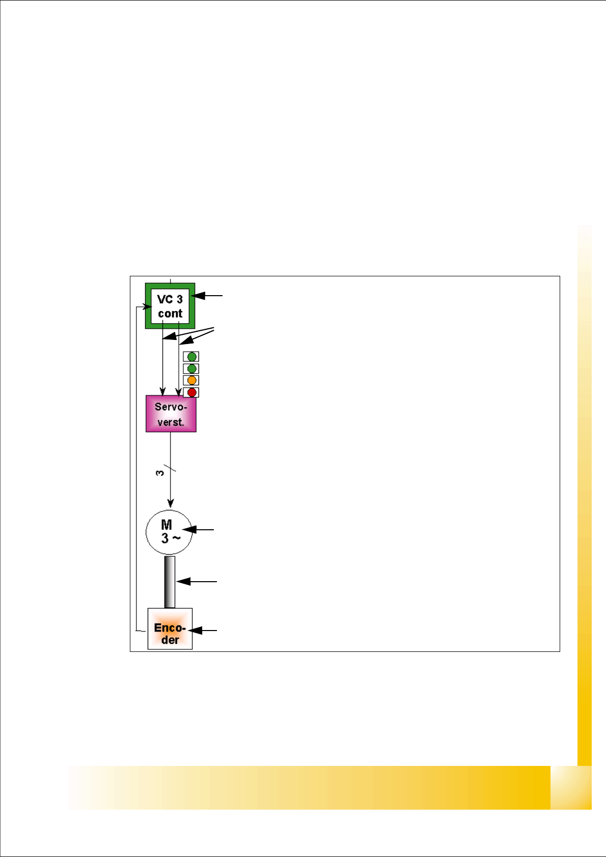
The closed-loop control system for control of the head axes consists of the following parts. Bet-
ween the head axes, some differences which will be explain later in this chapter.
– Axis controller ’A363’ with VC 3 Controller
– Servo card (SDS)
– Motor
– Measuring system (Incremental- scale and -encoder)
Fig. 6.6 - 1 Excample: Axis control for Star axis
Axis card A363 with VC 3 Controller (VC = Velocity Commutation)
Control signals I
nom "W" and I nom "U"
LED‘s on the Servo amplifier:
– Power supply ON
– Servo enable, if the the enable signal from the axis board available.
– Display R.M.S. current limiter shorter than 2,5 s.
– Error: Overvoltage, -current, -temperature or Nominal current-overstep-
ping longer than 2,5 sec.
Servo board control directly the motor.
3 Phase AC motor.
Between the motor and the incremental encoder exist a fixed mechanical
combination.
Incremental encoder: transmit the exact position of the axis via the track
signals.
1 - 80
Student Guide SIPLACE HF/HF3
6 Collect &Place-Head / DLM2 Edition 09/2005
80
6.6.1.1 Overview positioning time 12 segment C&P head
6
6.6.1.2 Overview positioning time 6 segment C&P head
6
6.6.2 Track signals head axes
The track signals undertake a meaning function in the case of the new drive concept of the HF
machine. They are responsible for the exactly and precise positioning of the axes and are used
as only response of the closed-loop control system so that the track signals have an important
influence on dynamics of the axes.
6.6.2.1 Overview
6
Axis Mode / Distance Positioning time
Star Axis continuous run / 1 Star step 46ms +/-3ms
Z absolute, free space / 685 digits 24ms, -1ms
Z
Light barrier bottom, into Calibration tool pocket / ca.
685 digits 24ms +/-3ms
DP 100 digits 13ms +/-3ms
DP 3600 digits 43ms +/-3ms
Table 6.6 - 1 Positioning time 12 segment C&P head DLM2
Axis Mode / Distance Positioning time
Star
Axis continuous run / 1 Star step 70ms +/-3ms
Z absolute, free space / 685 digits 30ms +/-3ms
Z
Light barrier bottom, into calibration tool pocket / approx.
685 digits 30ms +/-3ms
DP 200 digits 38ms +/-3ms
DP 7200 digits 85ms +/-3ms
Table 6.6 - 2 Positioning time 6 segment C&P head DLM2
Axes Mechanical settings Oszilloscope diagram
Star 6 25x: Resolution 1/1000° 6 digital track signal amplitude 3,6V
pp
6
Z 6 nothing 6 digital track signal amplitude 3,6V
pp
6
DP 6 DP-axis Incremental encoder adjustment
to the glass scale (segment)
1,5 mm 6
digital track signal amplitude 3,6V
pp
6
Tab. 6.6 - 3 Adjustments Oscilloscope
1 - 81
Student Guide SIPLACE HF/HF3
Edition 09/2005 6 Collect &Place-Head / DLM2
81
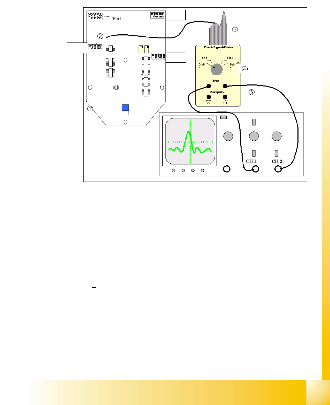
6.6.2.2 Test set up
Fig. 6.6 - 2 General test set up to check the track signals
X13 = Z-Axis
X15 = Star-Axis
X16 = DP-Axis 6
Connector description of the connectors X13, X15, X16:
The track signals of the head axes can only be measured as digital signals i.e. the transformation
of the analogous track signals into digital track signals occurs directly in the incremental encoder.
X13
X16
X15
1. Ground 2. Track A
3. Track A
4. Ground
5. Track B 6. Track B
7. +5V 8. Track N
9. Track N
10.Pin removed