SG_FSE_SiplaceHF_HF3_00193901-05_eng.pdf - 第315页
1 - 3 S tudent Guide SIPLACE HF/HF3 Edition 09/2005 7 TWIN-Head 3 7.1.2 Part s on the TWIN- Head Fig. 7.1 - 3 Parts TWIN- head 1. CAN Bus Processor board 2. Main board TWIN- head 3. D-axis com plete with in cremental enc…

1 - 2
Student Guide SIPLACE HF/HF3
7 TWIN-Head Edition 09/2005
2
7.1.1 Technical Data TWIN- Head
Fig. 7.1 - 2 Technical data TWIN- head
Placement accuracy (X/Y) 35µm by 4sigma with IC-camera
Placement accuracy (X/Y) 30µm by 4sigma with FC-camera
Placement accuracy (Angle) 0,07° by 4sigma
Placement speed 3500 cph
Maximum component size: 50 up to 40 mm single measurement on both segments
69 up to 10 mm multiple measurement by both segments
125 up to 10mm multiple measurement by one segment
200 up to 125mm multiple measurement with restriction
Max. component height 25 mm
Placement force 1-15 N (0,5 N with special nozzle)
D-Axis / Resolution direct drive / 0,001 degree
Z-Axis / Resolution Linear motor / 0,5 µm
Travel range Z-axis app. 60 mm
Nozzle types 5xx (4xx, 8xx, 9xx with adapter)
Distance between the segments approx. 71,00 mm
Max. weight of component 100g
1 - 3
Student Guide SIPLACE HF/HF3
Edition 09/2005 7 TWIN-Head
3
7.1.2 Parts on the TWIN- Head
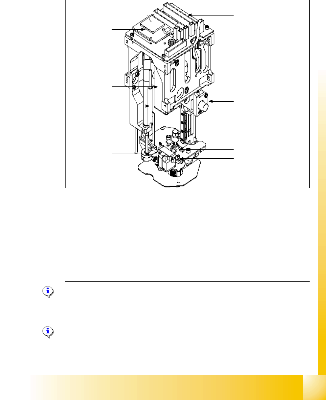
Fig. 7.1 - 3 Parts TWIN- head
1. CAN Bus Processor board
2. Main board TWIN- head
3. D-axis complete with incremental encoder and force sensor
4. Incremental encoder Z-axis
5. Retract unit to return the Z-axis in a safety area in case of power fail
6. Vacuum generator
7. Actuator retract unit (right) / Screw on D-Axis board (left)
Please Note:
Please use this two Positions (7) to move manually the Z-Axis downwards if the Servo board
switch off (Switch off the Axis card)!
Please Note:
The parts 1, 2, 4, 5 and 6 are spare parts and the whole module. ( Service manual).
4
3
2
5
1
6
7
7
1 - 4
Student Guide SIPLACE HF/HF3
7 TWIN-Head Edition 09/2005
4
7.1.2.1 Vacuum generator TWIN- Head
The vacuum generator controls the vacuum, air kiss and the zero balancing position (middle Po-
sition-->no vacuum and no air kiss) for the segments with a aid of a linear motor automatically.
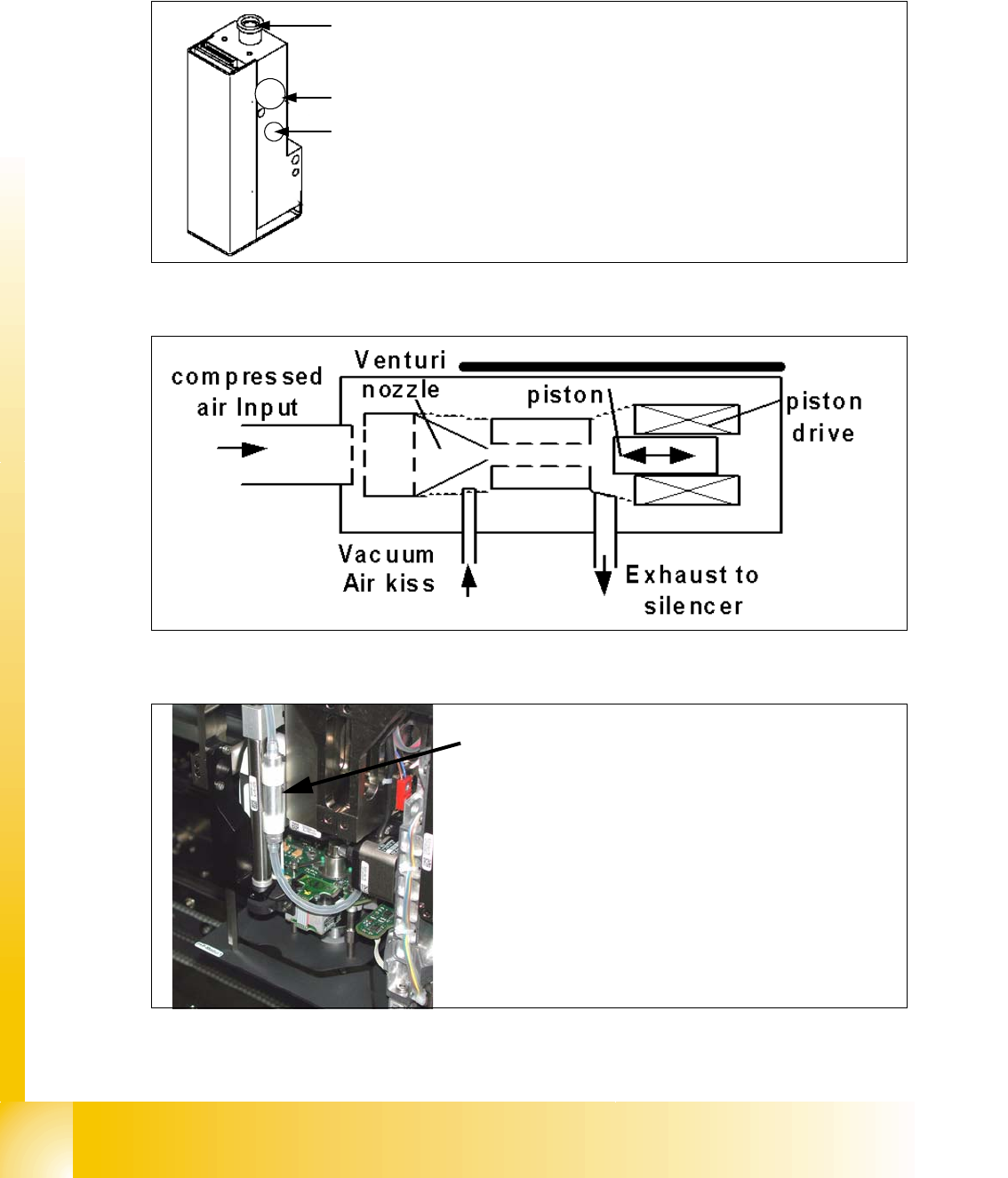
Fig. 7.1 - 4 Vacuum generator
Fig. 7.1 - 5 Principle of the vacuum generator
Fig. 7.1 - 6 Filter for the vacuum generator
1
3
2
1. Compressed air input
2. Exhaust air to the silencer and cooling the X-linear motor
3. Output vacuum that go to the D-axis motor through the
shaft of the motor and then to the nozzle.
Filter for the vacuum system on the TWIN- head.
The Filter is mounted on the retract unit and used as an
attenuator to control the vacuum. Together with the defi-
ned length of the silicon pipe reduce the attenuator the
oscillation of the vacuum generator and guaranteed an
accurate vacuum- and air kiss supply.