SG_FSE_SiplaceHF_HF3_00193901-05_eng.pdf - 第346页
1 - 34 S tudent Guide SIPLACE HF/HF3 7 TWIN-Head Edition 09/2005 34 7.4.6.5 Check the "Air kiss" pre ssure ➠ S tart SITEST . ➠ Move the gantry so that you can easily reach th e no zzle of the T win Head with on…
1 - 33
Student Guide SIPLACE HF/HF3
Edition 09/2005 7 TWIN-Head
33
7.4.6.4 Check the pressure tightness of the vacuum system
➠ Start SITEST.
➠ Move the gantry so that you can easily reach the nozzle of the Twin Head with one and the
keyboard with the other hand.
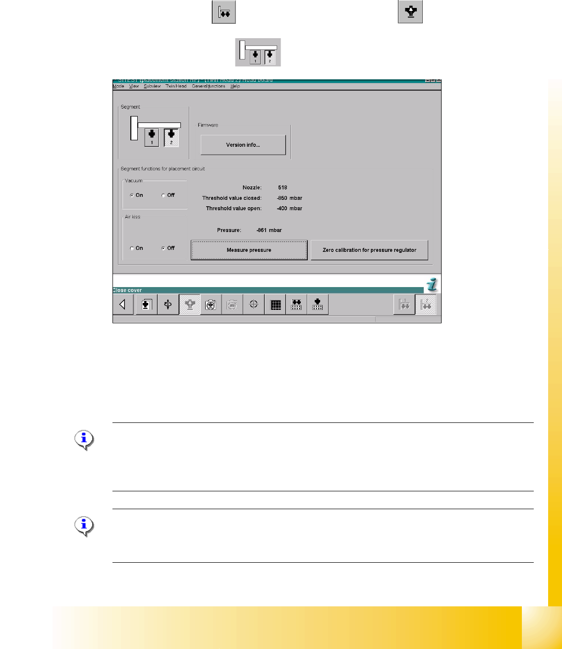
Sitest 7 ➠ Select "Twin head" ==> Select "Head board functions"
==>Select Twin module
fig. 7.4 - 11 SITEST functions head board functions
➠ Switch "on" the vacuum.
➠ Close the nozzle of the appropriate P&P module (e.g. by sealing it with your finger tip).
➠ Select "Measure pressure".
➠ The displayed value should be close to the "Threshold value closed".
Please Note:
"Threshold value closed" (or closed vacuum) defines the maximum vacuum.
"
Threshold value open" defines the maximal allowable vacuum value for the specific nozzle type
- in case that no nozzle is setup, the value "0" is shown.
Please Note:
The value "Vacuum closed" will be determined in the menue "Calibrate Twin head"==> "Vacuum
closed calibrate".
1 - 34
Student Guide SIPLACE HF/HF3
7 TWIN-Head Edition 09/2005
34
7.4.6.5 Check the "Air kiss" pressure
➠ Start SITEST.
➠ Move the gantry so that you can easily reach the nozzle of the Twin Head with one and the
keyboard with the other hand.
Please Note:
The value for the "Air kiss" pressure can be edited between 0 and 400 mbar. Standard value (only
for SITEST): 400 mbar 7
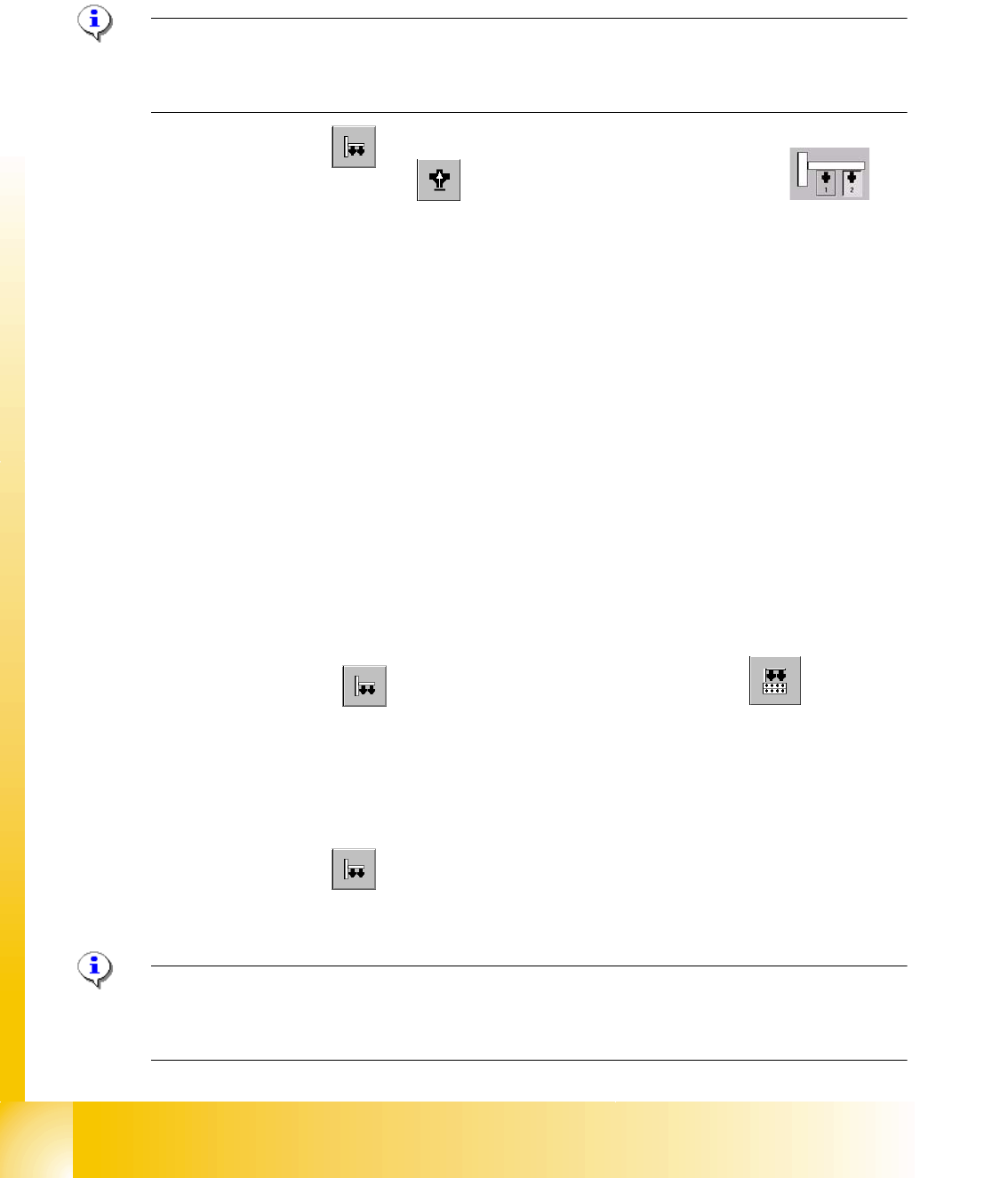
➠ Select "Twin Head"
Sitest: 7 ➠ Select "Head board functions" ==> Select the Twin module (segment)
➠ Switch "on" the air kiss.
➠ Close the nozzle of the appropriate Twin module (e.g. by sealing it with your finger tip).
➠ You can edit and modify the value for the forced air pressure or leave the standard value.
➠ Select "Measure pressure".
➠ The measured value should correspond (approx.) with the given value.
7.4.7 Calibrating the Twin Head
During initial set-up or after replacement of a Twin module the Twin Head must be calibrated. The
Offset between TWIN Segment and PCB-camera center is meassured.
7
➠ Put the nozzles 517 by hand on the segments of the P&P modules.
➠ Make sure that the first nozzle from the garages are empty and depend on this the filling
level from the nozzle changer are edited
, this is necessary for the calibration of the pick-up
height.
➠ Enter the nozzle "517" for both Twin modules as active nozzle on the Twin Head:
Sitest: 7 ==> Select "Twin Head" ==> Select "nozzle changer head functions" 7
7
==> Select the appropriate "segment" out of the list. 7
==> Select "Edit" ==> Select "517" and "accept". 7
==> Activate the checkbox "selected segment". 7
==> Select "Confirm exchange". 7
7
➠ Select "Twin Head" ==> Select "Calibrate machine"
==> Activate only "Twin Head" of the appropriate placement area.
==> Select "Start".
Please Note: The following points are calibrate automatically:
- MA-Zero point, PCB Camera, Calibration tool position, Head height, TH calibration Offset modul
1and 2, IC Camera, (option FC Camera) Nozzle changer. 7
1 - 35
Student Guide SIPLACE HF/HF3
Edition 09/2005 7 TWIN-Head
35
7.4.8 Mechanical adjustment the incremental encoder Z-axis
Please Note:
The incremental encoder on the Z-Axis must be adjust to a distance of 0,4 mm +/- 0,1 mm to the
incremental scale. Please adjust the incremental encoder parallel to the incremental scale. For the
distance use a plastic feeler gauge of 0,4 mm.
After this adjustment of the incremental encoder you have to check the zero pulse and track sig-
nals (see chapter Tracksignals and Zeropulse).
Notes