SG_FSE_SiplaceHF_HF3_00193901-05_eng.pdf - 第221页
1 - 21 S tudent Guide SIPLACE HF/HF3 Edition 09/2005 6 Colle ct &Place-Head / DLM2 21 6.2.9 Pollution and Component s are Rejected / Nozzles T urned to 0° Fig. 6.2 - 9 Sequence vacuumcheck – The Gantry axes move the …
1 - 20
Student Guide SIPLACE HF/HF3
6 Collect &Place-Head / DLM2 Edition 09/2005
20
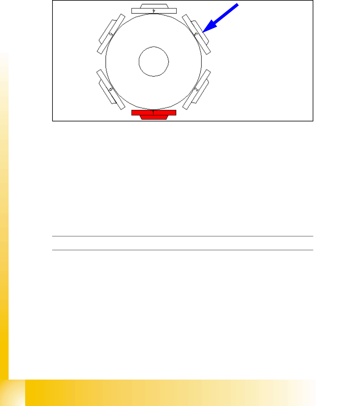
6.2.8 Reference Run at Dp-axis
The function of the DP axis is, to turn the nozzle in the correct pick up angle. After the component
recognition the DP-axis turn the components in correct placement angle.
Fig. 6.2 - 8 Reference run at DP-axis
– The segment now in the DP-station is turned to reference position. (Segment 3 at 6 nozzle
head / Segment 5 at 12 nozzle head.)
– Sequence: the DP-station swivels in. The axis starts and searches for the zero pulse. The Zero
pulse is checked on failure. The DP-station swivels out after the end signal.
– The swiveling function is controlled by the CAN-Bus.
– Turning the sleeve is controlled by the axis controller with signals from DP-position encoder.
– The zero point correction on the DP-axis is always 0 (because up to 12 segments are operated
by one drive).
C&P Head Reference run finished!
1 - 21
Student Guide SIPLACE HF/HF3
Edition 09/2005 6 Collect &Place-Head / DLM2
21
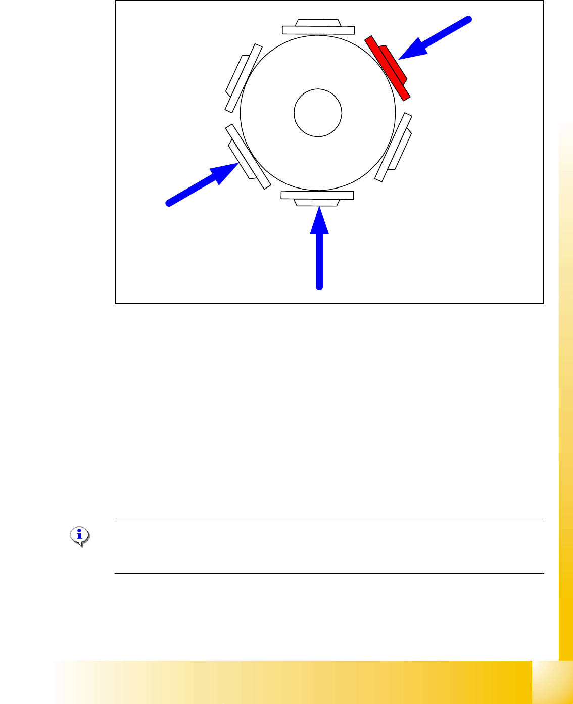
6.2.9 Pollution and Components are Rejected / Nozzles Turned to 0°
Fig. 6.2 - 9 Sequence vacuumcheck
– The Gantry axes move the Collect & Place head to the reject position.
– The star axes move anticlockwise and all three functions are carried out within a head cycle
and at same time (see Fig. 6.2 - 9).
1. The DP-station is swiveled in and turns each segment to 0° position.
2. The air kiss valve is opened, the valve drive of the reject position is activated and switches
between open and closed. Anything on the nozzle is rejected.The air kiss valve is closed.
3. The vacuum reference values at the pick-up
/ placement station are measured.
– These are the reference values for each segment for the vacuum checks during placement.
– These three steps are executed parallel.
Note:
The position 2 in Fig. 6.2 - 9 will used only on the HS and S/F Machine. The reject position on the
Siplace HF is below at position 3.
4
1
5
2
3
6
1
3
2
1 - 22
Student Guide SIPLACE HF/HF3
6 Collect &Place-Head / DLM2 Edition 09/2005
22
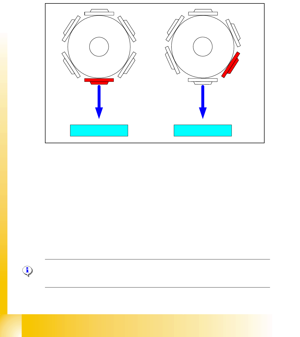
6.2.10 Height reference run
With this function we check the correct fitting on the sleeve and the correct nozzle type which is
programmed.
The nozzle length is taken to calculate the pick up and placement height for the following place-
ments.
Fig. 6.2 - 10 Measure nozzle height
1. Top of the fixed conveyor rail
2. First step with segment 1 for measure the nozzle height.
3. Last step with segment 6 (12) for measure the nozzle height.
– The gantry moves the placement heads above the fixed conveyor rail.
– The Z- axis runs down, and all nozzles touch the transport rail.
– Nozzle 1 defines the reference length.
– All segments are measured according to there specific length reffering to nozzle 1.
– The maximum length tolerance is 0,4 mm: If the length difference is too high an error message
is displayed.
Please Note
Exception: special nozzle with type number X9X are only measured (there is no length specifica-
tion).
4
1
5
2
3
6
4
1
5
2
3
6
1
23