SG_FSE_SiplaceHF_HF3_00193901-05_eng.pdf - 第70页
1 - 44 S tudent Guide SIPLACE HF/HF3 2 Overview Edition 09/2005 44 2.2.17.3 Construction dual conveyor Dual conveyor has two transportation tracks (1 an d 2). At the standard conveyor , the fixed con- veyorside f rom eve…
1 - 43
Student Guide SIPLACE HF/HF3
Edition 09/2005 2 Overview
43
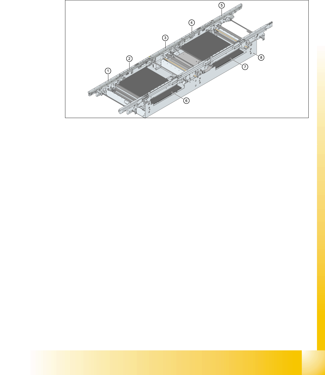
2.2.17.2 Construction single conveyor
The single conveyor consist oft the input conveyor, two placements areas, intermediate conveyor
and output conveyor. Every conveyor had an automatic width adjustment and a lifting table for
clamping the PCB..
2
Fig. 2.2 - 30 Construction PCB conveyor
1. Input conveyor
2. Conveyor at placement area 1
3. Intermediate conveyor
4. Conveyor at placement area 2
5. Output conveyor
6. Lifting table 1
7. Lifting table 2
8. mounting frame transport
1 - 44
Student Guide SIPLACE HF/HF3
2 Overview Edition 09/2005
44
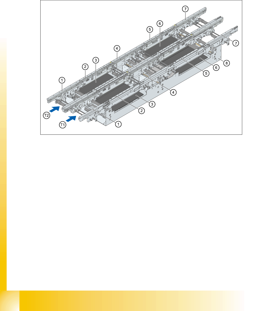
2.2.17.3 Construction dual conveyor
Dual conveyor has two transportation tracks (1 and 2). At the standard conveyor, the fixed con-
veyorside from every transportation track is on the right side. The fixed conveyor side on the left
side is available.
2
Fig. 2.2 - 31 Construction dual conveyor
1. Input conveyor
2. Conveyor at placement area 1
3. Lifting table PA 1
4. Intermediate conveyor
5. Conveyor at placement area 2
6. Lifting table PA 2
7. Output conveyor
8. mounting frame of transport

Student Guide SIPLACE HF/HF3
Edition 09/2005 Contents
1
Chapter
Table of Contents
3 Communication and Control . . . . . . . . . . . . . . . . . . . . . . . . . . . . . . . . . . . . . . . . . . 3
3.1 Networking . . . . . . . . . . . . . . . . . . . . . . . . . . . . . . . . . . . . . . . . . . . . . . . . . . . . . . . . . . . . . . . . . . . . . 3
3.1.1 Communication Overview . . . . . . . . . . . . . . . . . . . . . . . . . . . . . . . . . . . . . . . . . . . . . . 3
3.1.2 Networking Overview. . . . . . . . . . . . . . . . . . . . . . . . . . . . . . . . . . . . . . . . . . . . . . . . . . 4
3.2 Networking Address . . . . . . . . . . . . . . . . . . . . . . . . . . . . . . . . . . . . . . . . . . . . . . . . . . . . . . . . . . . . . 5
3.2.1 Computer at the LAN Network . . . . . . . . . . . . . . . . . . . . . . . . . . . . . . . . . . . . . . . . . . 6
3.2.2 Communication on HF placement machine. . . . . . . . . . . . . . . . . . . . . . . . . . . . . . . . . 7
3.2.3 Machine Controller Communication . . . . . . . . . . . . . . . . . . . . . . . . . . . . . . . . . . . . . . 8
3.3 CAN Bus . . . . . . . . . . . . . . . . . . . . . . . . . . . . . . . . . . . . . . . . . . . . . . . . . . . . . . . . . . . . . . . . . . . . . . . 9
3.3.1 History of CAN. . . . . . . . . . . . . . . . . . . . . . . . . . . . . . . . . . . . . . . . . . . . . . . . . . . . . . . 9
3.3.2 CAN Bus in General . . . . . . . . . . . . . . . . . . . . . . . . . . . . . . . . . . . . . . . . . . . . . . . . . 11
3.3.2.1 11 Bit Identifier . . . . . . . . . . . . . . . . . . . . . . . . . . . . . . . . . . . . . . . . . . . . . . . . . . 12
3.3.2.2 CAN Bus protocol. . . . . . . . . . . . . . . . . . . . . . . . . . . . . . . . . . . . . . . . . . . . . . . . 12
3.3.2.3 CSMA: Collusion Detectection . . . . . . . . . . . . . . . . . . . . . . . . . . . . . . . . . . . . . . 13
3.3.2.4 CAN Bus Arbitration . . . . . . . . . . . . . . . . . . . . . . . . . . . . . . . . . . . . . . . . . . . . . . 13
3.3.3 CAN Bus Concept on HF machine(up to MA.No. xx) . . . . . . . . . . . . . . . . . . . . . . . . 15
3.3.4 CAN Bus Concept on HF machine from MA. No. xx. . . . . . . . . . . . . . . . . . . . . . . . . 16
3.3.5 CAN Bus Concept on HF3 machine . . . . . . . . . . . . . . . . . . . . . . . . . . . . . . . . . . . . . 17
3.3.6 CAN-Bus Concept with One Wire Bus e.g. HF3-Machine. . . . . . . . . . . . . . . . . . . . . 18
3.3.7 CAN Bus Processor Board C&P Head . . . . . . . . . . . . . . . . . . . . . . . . . . . . . . . . . . . 19
3.3.7.1 CAN Bus controlled function on C&P Head . . . . . . . . . . . . . . . . . . . . . . . . . . . . 19
3.3.8 CAN Bus Processor Board Twin Head . . . . . . . . . . . . . . . . . . . . . . . . . . . . . . . . . . . 20
3.3.8.1 CAN bus controlled Head Functions Twin Head . . . . . . . . . . . . . . . . . . . . . . . . 21
3.3.9 CAN I/O Module (SLIO) HF up to MA.No. xx . . . . . . . . . . . . . . . . . . . . . . . . . . . . . . 22
3.3.9.1 Connector on I/O module . . . . . . . . . . . . . . . . . . . . . . . . . . . . . . . . . . . . . . . . . . 23
3.3.9.2 CAN I/O module sector 2, main distributor. . . . . . . . . . . . . . . . . . . . . . . . . . . . . 23
3.3.9.3 CAN I/O in sub-distributor section 4. . . . . . . . . . . . . . . . . . . . . . . . . . . . . . . . . . 25
3.3.10 CAN I/O Module (SLIO) HF from MA.No. xx . . . . . . . . . . . . . . . . . . . . . . . . . . . . . . 27
3.3.11 CAN: Bus Communication with Axis Controller. . . . . . . . . . . . . . . . . . . . . . . . . . . . 32
3.3.12 CAN Bus Communication with Vision system. . . . . . . . . . . . . . . . . . . . . . . . . . . . . 32
3.3.12.1 Visionsystem: Flash-Signal . . . . . . . . . . . . . . . . . . . . . . . . . . . . . . . . . . . . . . . 33
3.4 Axis control . . . . . . . . . . . . . . . . . . . . . . . . . . . . . . . . . . . . . . . . . . . . . . . . . . . . . . . . . . . . . . . . . . . 35
3.4.1 Position measuring system . . . . . . . . . . . . . . . . . . . . . . . . . . . . . . . . . . . . . . . . . . . . 35
3.4.1.1 Track signals and Zero pulse signal. . . . . . . . . . . . . . . . . . . . . . . . . . . . . . . . . . 35
3.4.1.2 Zero pulse at the position encoder. . . . . . . . . . . . . . . . . . . . . . . . . . . . . . . . . . . 37