SG_FSE_SiplaceHF_HF3_00193901-05_eng.pdf - 第166页
1 - 2 S tudent Guide SIPLACE HF/HF3 Contents Edition 09/2005 2

Student Guide SIPLACE HF/HF3
Edition 09/2005 Contents
1
Chapter
Table of Contents
5 Gantry. . . . . . . . . . . . . . . . . . . . . . . . . . . . . . . . . . . . . . . . . . . . . . . . . . . . . . . . . . . . . 1
5.1 Overview Gantry . . . . . . . . . . . . . . . . . . . . . . . . . . . . . . . . . . . . . . . . . . . . . . . . . . . . . . . . . . . . . . . . 1
5.1.1 Mechanical structur of the X- and Y- axes. . . . . . . . . . . . . . . . . . . . . . . . . . . . . . . . . . 3
5.1.2 Pneumatic connectors on the gantry. . . . . . . . . . . . . . . . . . . . . . . . . . . . . . . . . . . . . . 4
5.2 Reference run Gantry . . . . . . . . . . . . . . . . . . . . . . . . . . . . . . . . . . . . . . . . . . . . . . . . . . . . . . . . . . . . 5
5.2.1 Sequence reference run at X- and Y-axis . . . . . . . . . . . . . . . . . . . . . . . . . . . . . . . . . . 5
5.2.2 X and Y commutation position search. . . . . . . . . . . . . . . . . . . . . . . . . . . . . . . . . . . . . 6
5.2.3 Reference run of X- and Y- axes. . . . . . . . . . . . . . . . . . . . . . . . . . . . . . . . . . . . . . . . . 6
5.2.4 Initialization Transport system. . . . . . . . . . . . . . . . . . . . . . . . . . . . . . . . . . . . . . . . . . . 7
5.3 Adjustments . . . . . . . . . . . . . . . . . . . . . . . . . . . . . . . . . . . . . . . . . . . . . . . . . . . . . . . . . . . . . . . . . . . . 9
5.3.1 Travel range and velocity monitoring X- and Y- Axes on the HF. . . . . . . . . . . . . . . . . 9
5.3.2 Travel range and velocity monitoring X- and Y- Axes on the HF 3 . . . . . . . . . . . . . . 10
5.3.2.1 Adjustments BERO‘s . . . . . . . . . . . . . . . . . . . . . . . . . . . . . . . . . . . . . . . . . . . . . 11
5.3.2.2 Description of the BERO‘s on the Y-Axis . . . . . . . . . . . . . . . . . . . . . . . . . . . . . . 11
5.3.3 Check the DIP Switches . . . . . . . . . . . . . . . . . . . . . . . . . . . . . . . . . . . . . . . . . . . . . . 12
5.3.3.1 DIP Switches on the head interface . . . . . . . . . . . . . . . . . . . . . . . . . . . . . . . . . . 12
5.3.3.2 DIP Switches on the vision board. . . . . . . . . . . . . . . . . . . . . . . . . . . . . . . . . . . . 13
5.3.4 Anti crash board . . . . . . . . . . . . . . . . . . . . . . . . . . . . . . . . . . . . . . . . . . . . . . . . . . . . 14
5.3.5 Mechanical adjustment the incremental encoder . . . . . . . . . . . . . . . . . . . . . . . . . . . 15
5.4 Track signals and Zero pulse . . . . . . . . . . . . . . . . . . . . . . . . . . . . . . . . . . . . . . . . . . . . . . . . . . . . . 17
5.4.1 Check the zero pulse signal . . . . . . . . . . . . . . . . . . . . . . . . . . . . . . . . . . . . . . . . . . . 17
5.4.1.1 Measurement the analog zero pulse signal . . . . . . . . . . . . . . . . . . . . . . . . . . . . 17
5.4.1.2 Measurement the digital zero pulse signal. . . . . . . . . . . . . . . . . . . . . . . . . . . . . 19
5.4.2 Check the track signals . . . . . . . . . . . . . . . . . . . . . . . . . . . . . . . . . . . . . . . . . . . . . . . 21
5.4.2.1 Analog track signals . . . . . . . . . . . . . . . . . . . . . . . . . . . . . . . . . . . . . . . . . . . . . . 21
5.4.2.2 Digital Track signals . . . . . . . . . . . . . . . . . . . . . . . . . . . . . . . . . . . . . . . . . . . . . . 22
5.5 Axis control . . . . . . . . . . . . . . . . . . . . . . . . . . . . . . . . . . . . . . . . . . . . . . . . . . . . . . . . . . . . . . . . . . . 23
5.5.1 Parts for the axis control . . . . . . . . . . . . . . . . . . . . . . . . . . . . . . . . . . . . . . . . . . . . . . 23
5.5.2 Check dynamic X-axis. . . . . . . . . . . . . . . . . . . . . . . . . . . . . . . . . . . . . . . . . . . . . . . . 24
5.5.2.1 Test setup with Axis testbox. . . . . . . . . . . . . . . . . . . . . . . . . . . . . . . . . . . . . . . . 24
5.5.2.2 Test setup with SAT-Box . . . . . . . . . . . . . . . . . . . . . . . . . . . . . . . . . . . . . . . . . . 25
5.5.3 Check dynamic Y-axis. . . . . . . . . . . . . . . . . . . . . . . . . . . . . . . . . . . . . . . . . . . . . . . . 28
5.5.3.1 Test setup. . . . . . . . . . . . . . . . . . . . . . . . . . . . . . . . . . . . . . . . . . . . . . . . . . . . . . 29

1 - 2
Student Guide SIPLACE HF/HF3
Contents Edition 09/2005
2
1 - 1
Student Guide SIPLACE HF/HF3
Edition 09/2005 5 Gantry
1
5Gantry
5.1 Overview Gantry
The 2 gantries of the HF machine or the three gantries of the HF3 machine consist of one X- and
one Y - axis. Both axes are driven by a linear motor which is equipped with an integrated temper-
ature sensor. The Y-axis moves from the right to the left side in positive counting direction if you
look in transportation direction, the X-axis moves from the the input conveyor to the output con-
veyer in positive counting direction. The placement heads are mounted on the head plates of the
respective X axis.
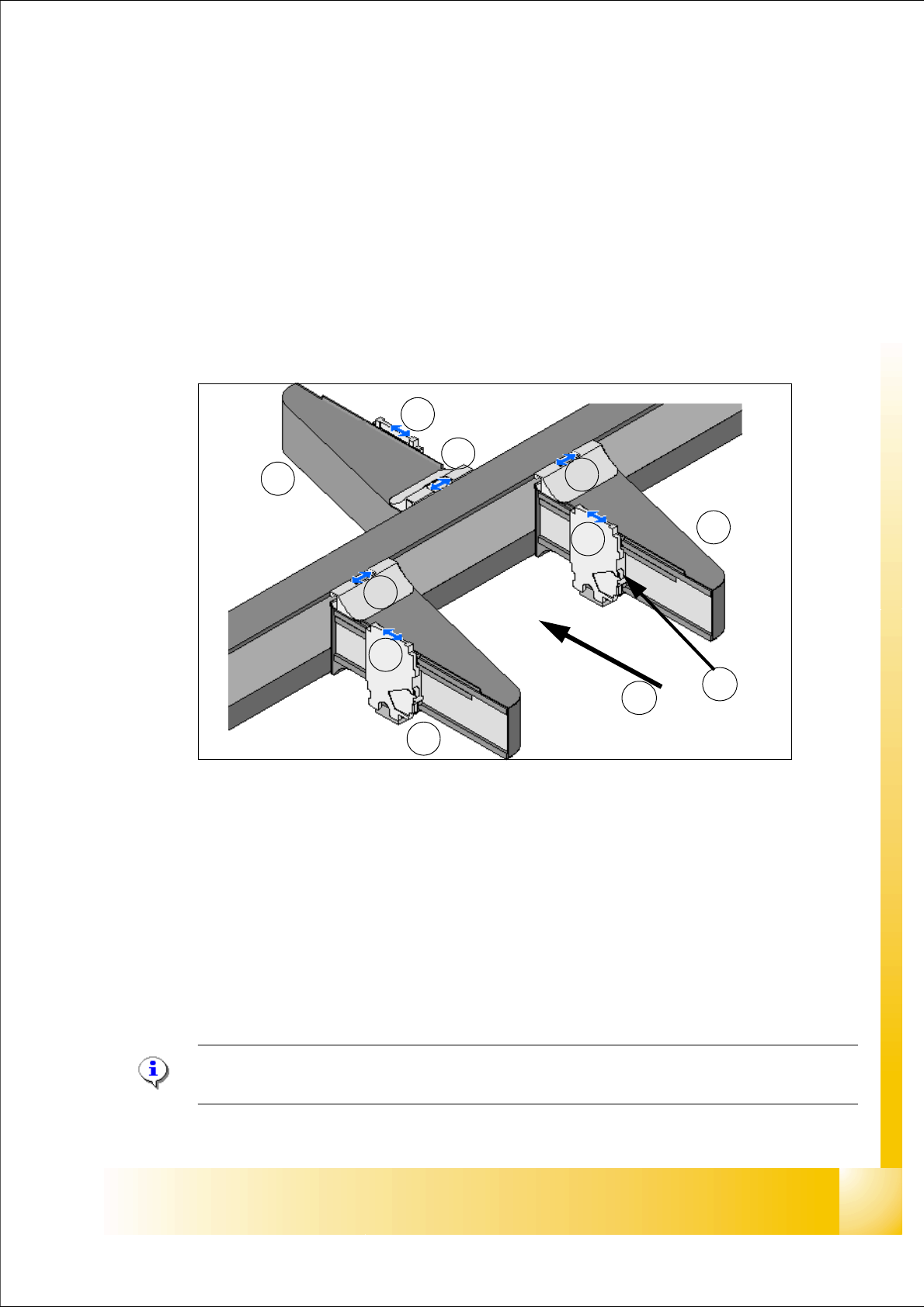
Fig. 5.1 - 1 Position of the gantries HF3
Legend:
Please Note: On the HF machine are only two gantries. The name of this Gantries with Sta-
tionsoftware 505.xx are Gantry 1 and Gantry 3.
G1Gantry 1 in PA1 G3Gantry 3 in PA2
X1X-Axis, Gantry 1 X3X-Axis, Gantry 3
Y1Y-Axis, Gantry 1 Y3Y-Axis, Gantry 3
G4Gantry 4 in PA 1
X4X-Axis, Gantry 4 (T)Transportation direction
Y4Y-Axis, Gantry 4 (TS)Temperature sensor on each head mounting plate
G4
G1
G3
Y4
Y3
Y1
X4
X3
X1
T
TS