SG_FSE_SiplaceHF_HF3_00193901-05_eng.pdf - 第40页
1 - 14 S tudent Guide SIPLACE HF/HF3 2 Overview Edition 09/2005 14 2.2.3.1 Pneumatic loop Cooling Y - Linear motor for Placem ent area 1/2 For cooling the Y -motors, an additional pneumatic system which is supplied by am…
1 - 13
Student Guide SIPLACE HF/HF3
Edition 09/2005 2 Overview
13
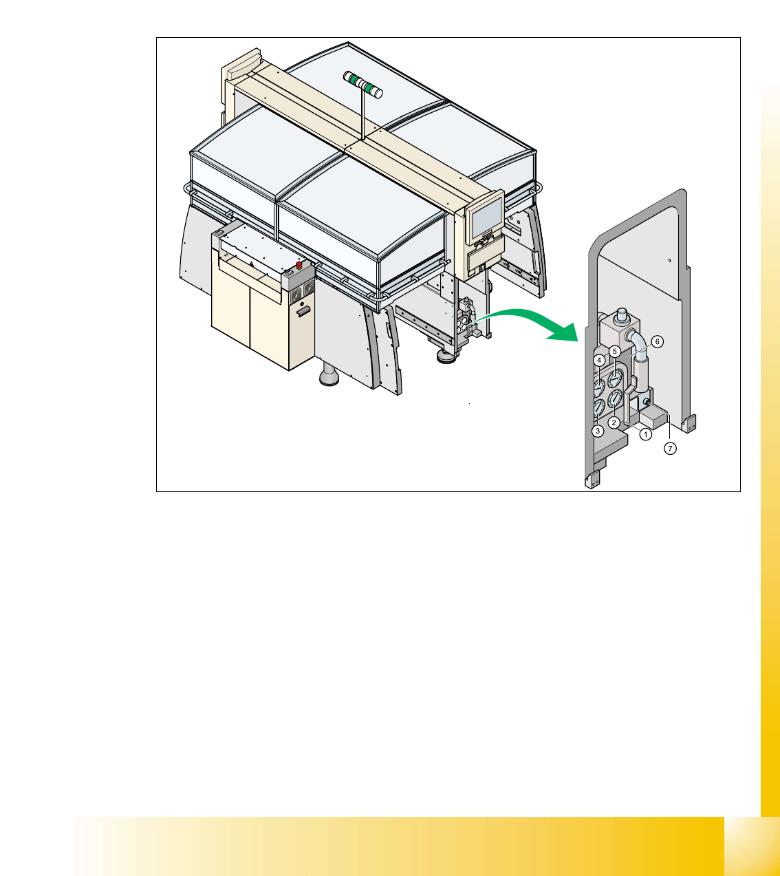
2.2.3 Pneumatic unit
The pneumatic unit is mounted on a compact slide-in module, and located on the right side of the
middle section. A lockable door prevents access to the unit.
Open you the cover of the pneumatic unit with machine key. In the pneumatic unit contain the
whole sensors and valves of the compressed air supply. The SMEMA (Siemens) PCB interface to
the previous and next stations is mounted in a seperate rack.
Fig. 2.2 - 5 Pneumatic unit as slide in module
(1) Manuell shut-off main valve
(2) Manometer for machine components
(3) Manometer for compressed air into the gantry distributor (0 - 0,6 MPa, 0 - 6 bar)
(4) Manometer for Bulkcase-Feeder and nozzle changer
(5) Main input manometer
(6) Filter compressed air
(7) Screw, for opening and move out the pneumatic unit

1 - 14
Student Guide SIPLACE HF/HF3
2 Overview Edition 09/2005
14
2.2.3.1 Pneumatic loop Cooling Y - Linear motor for Placement area 1/2
For cooling the Y-motors, an additional pneumatic system which is supplied by ambient air was
built up. The ambient air is sucked over a filter with the aid of a blower motor and provided to the
Y-motors. The compressed air escapes on the side of the Y-motor again.
2.2.3.2 Pneumatic loop Cooling X - Linear motor for Placement area 1/2
Cooling the X-motors is implemented via exhaust air of the vacuum generator of the C&P head or
Twin head.
2.2.3.3 Compressed air distributor block
The pneumatic unit is used to prepare and distribute the compressed air required in the machine.
The pressure in the compressed-air connection is 5,0 bar.
The following pneumatic circuits are supported via the compressed air distributor block:
– Gantrys 1-4 Vacuumgenerator: 5,0 bar
– Transportsystem: 5,0 bar
– Tape cutter for the locations 1-4: 5,0 bar
– Nozzle changer for the locations 1-4: 5,0 bar
– Docking units for the component changeover table: 5,0 bar
– Bulkase Feeder on the location 1-4: 2,5 bar
1 - 15
Student Guide SIPLACE HF/HF3
Edition 09/2005 2 Overview
15
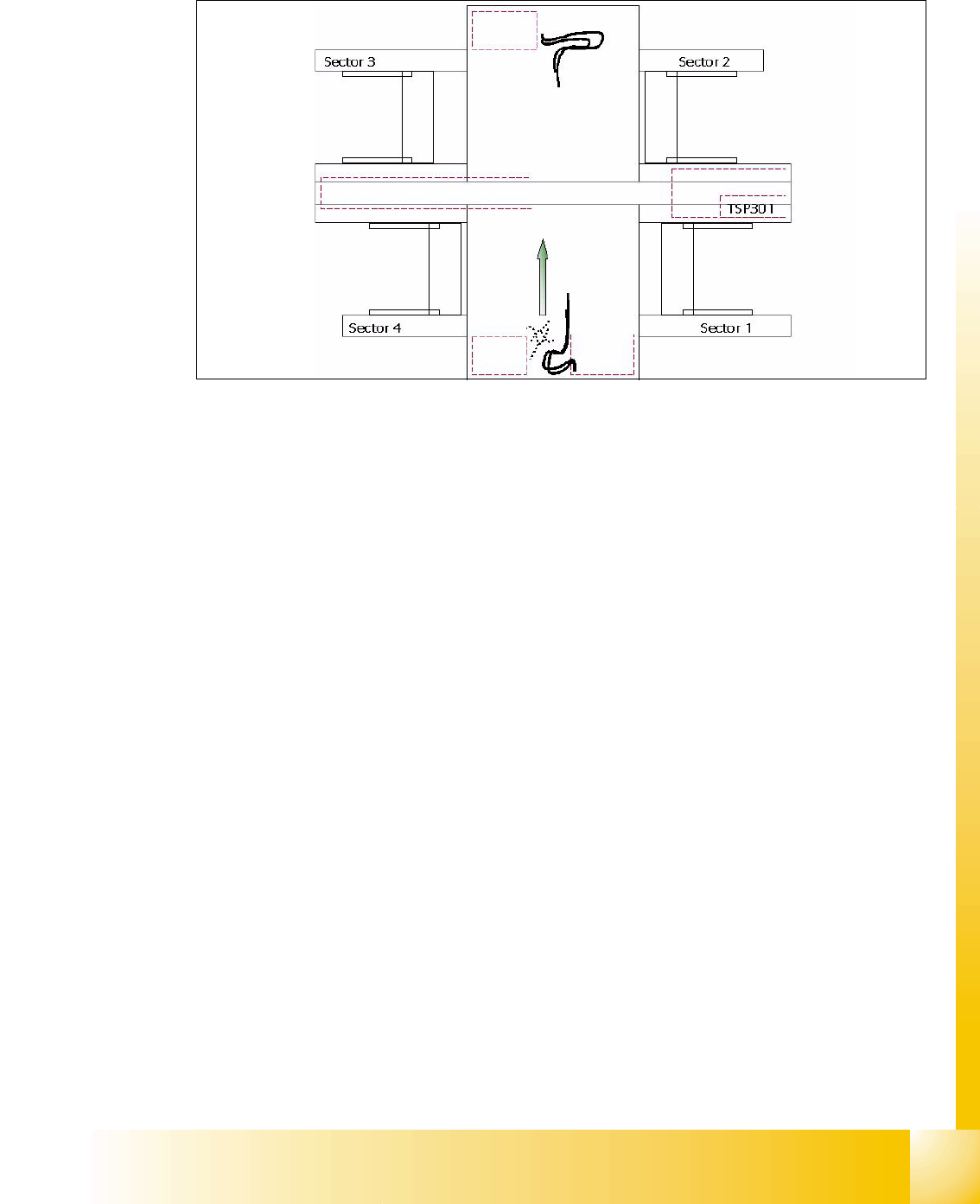
2.2.4 Sectors 1 - 4
Fig. 2.2 - 6 Overview Sector 1-4
Sector 1/3: 2
– Connector modules for safety loop and Start/Stop switch
– circuit for onehand operated comp.tables at location 1/3 respective sector 3 for location 3/4.
– Sector 1-> Hub for the Option Splicedetection
Sector 2 (Main Distributor): 2
– CAN I/O Module
– Vision illumination control board for Twin head IC-Camera or FC Camera (Option)
– DC/DC converter for Twin head IC-Camera (Flash signal)
– Main distributor (Connector moduls)
– Terminals X1qa (GND,+5V,+15V,-15V,+24V,.Start/Stop-signal, Covers, emergency stop sig-
nal,SW-enabling signal)
– Connector modules for safety loop and Start/Stop switch
Sector 4 (Sub Distributor): 2
– CAN I/O Modul
– Vision illumination control board for Twin head IC-Camera or FC Camera (Option)
– DC-distributer for Twin head IC-Camera (Flashsignal) in Placement area 1 if installed.
– Sub distributor (Connector moduls)
– Terminals X1ra (GND,+5V,+15V,-15V,+24V,Start/Stop-signal, Covers, E-stop signal,...)
– Connector modules for safety loop and Start/Stop switch
Axis unit PA 2
Axis unit PA 1 HF3