SG_FSE_SiplaceHF_HF3_00193901-05_eng.pdf - 第227页
1 - 27 S tudent Guide SIPLACE HF/HF3 Edition 09/2005 6 Colle ct &Place-Head / DLM2 27 6.3.7 Pick up first Component Fig. 6.3 - 7 Pick up first component 6.3.8 Pick up 6th component Fig. 6.3 - 8 Pick up 6th component …
1 - 26
Student Guide SIPLACE HF/HF3
6 Collect &Place-Head / DLM2 Edition 09/2005
26
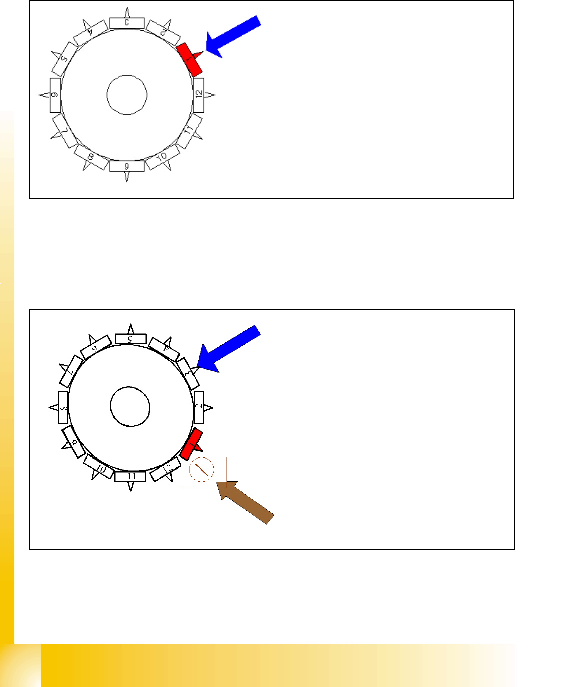
6.3.5 Turn nozzle 1 to Pick up angle (0° or 90°)
Fig. 6.3 - 5 Turn nozzle 1 to Pick up angle (0° or 90°)
The remaining nozzles on the head are turned to their pick up angles as the star steps
6.3.6 Check nozzle length for component recognition
Fig. 6.3 - 6 Check the nozzle length for component recognition in the comp. sensor
Star position 240°
– The star-axis is turned to 240° (equivalent to
240000 Digits). Now the nozzle 1 is in DP-station.
– DP-station swivels in and the DP-axis controller
system turns the rectangular nozzle to their 0° or 90
° Pick up angle (Standard pick up angle´s).
– When the nozzle is in position the end signal is trig-
gered and the DP-station swivels off.
Component sensor (option) measures at
315°:
– the component sensor measures the noz-
zle length.
– The measured length before pickup is ver-
ified with the reference length
– A length difernce of +0.15 mm or -0.1 mm
generate a error message and gantry
move immediatelly to Service position.
– The measurement in the component sen-
sor happens at full movement of the star
axis -"on the fly"- .
1 - 27
Student Guide SIPLACE HF/HF3
Edition 09/2005 6 Collect &Place-Head / DLM2
27
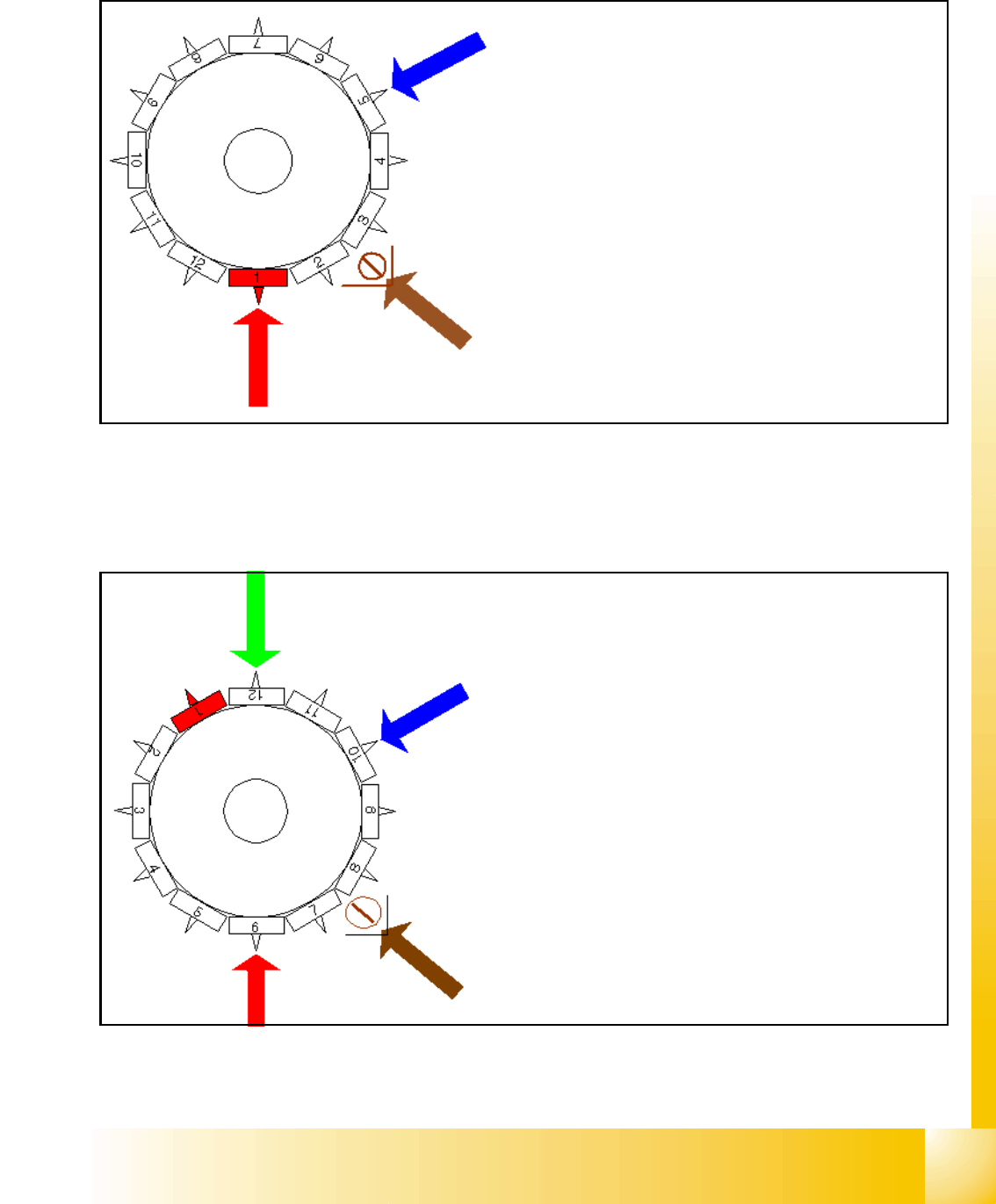
6.3.7 Pick up first Component
Fig. 6.3 - 7 Pick up first component
6.3.8 Pick up 6th component
Fig. 6.3 - 8 Pick up 6th component
Star position 0°
– Vision system: no action
– DP-station: turn nozzle 5 to Pick up angle
– pick up / placement station: pick up first component
– component sensor: during the next Star step the
nozzle length of segment 3 is measured
The remaining nozzles now pick up the components as
the star is stepped.
Star position 150°
– Vision system: no action
– DP-station: turn nozzle 10 to Pick up angle
– pick up / placement station: pick up 6th component
– synchronization: communication with MVS for the
optical centering of components.
– component sensor: during the next Star step the
nozzle length of segment 8 is measured
1 - 28
Student Guide SIPLACE HF/HF3
6 Collect &Place-Head / DLM2 Edition 09/2005
28
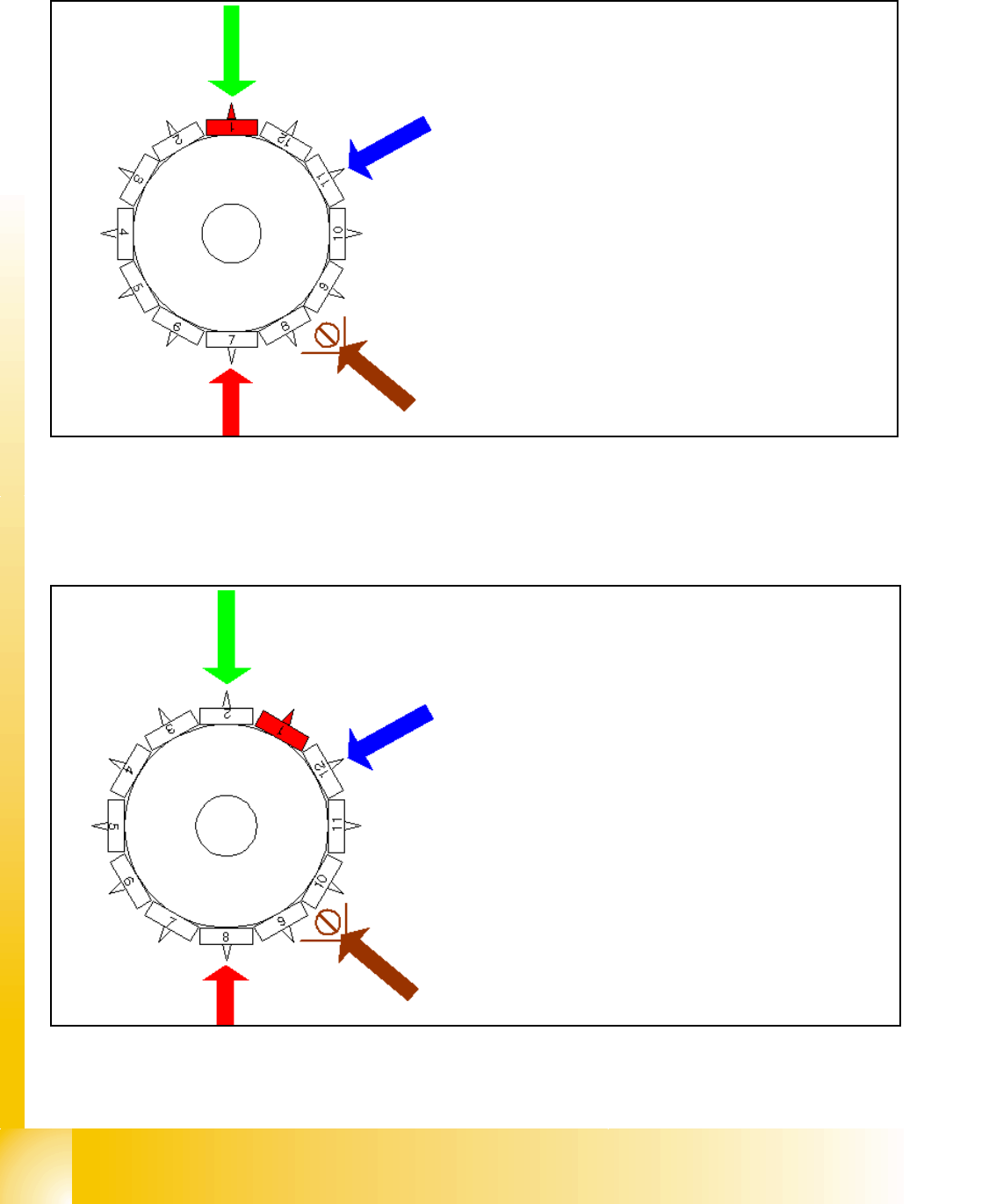
6.3.9 Pick up 7th component
Fig. 6.3 - 9 Pick up 7th component
6.3.10 Pick up 8th component
Fig. 6.3 - 10 Pick up 8th component
Star position 180°
– Vision system: component on segment 1 is cen-
tered.
– DP-station: turn nozzle 11 to Pick up angle
– pick up / placement station: pick up 7th component
– synchronization: communication with MVS for the
optical centering of components.
– component sensor: during the next Star step the
nozzle length of segment 9 is measured
Star position 210°
– Visionsystem: component on segment 2 is centered.
– DP-station: nozzle on segment 12 is turned to pick up
angle.
– pick up / placement station: pick up 8th componen
– component sensor: during the next Star step the noz-
zle length of segment 10 is measured