SG_FSE_SiplaceHF_HF3_00193901-05_eng.pdf - 第492页
1 - 18 S tudent Guide SIPLACE HF/HF3 1 1 MTC 2 Edition 09/2005 18 1 1.2.1 Incorporatin g the MTC in the SIPLACE st ation Fig. 1 1.2 - 1 The interfaces and power supply of the MTC 2 ( shown for tower 1) 1 1.2.1.1 CAN bus …

1 - 17
Student Guide SIPLACE HF/HF3
Edition 09/2005 11 MTC 2
17
11.2 Construction and mode of operation
The MTC 2 extends the capacity of a SIPLACE station to supply components by up to 100 JEDEC
waffle pack trays. It has its own controller (C167 controller board) and is integrated into the station
computer software. The setup of the MTC 2 is integrated into the line controller software of a sys-
tem.
Each of the two towers of the MTC 2 comprise a lifting axis and a feed axis. The lifting axes can
be set up with a large number of waffle pack trays in cassettes and transport these vertically. The
feed axes transport waffle pack trays which have been set up horizontally to the transfer position
to the SIPLACE station.
All drive units comprise Masterdrive drive systems:
The servo motors of the lifting axes each drive a spindle via a dual toothed belt, which trans-
ports vertically the cassettes which have been set up. A holding brake in the motors, which is
controlled by the Masterdrive via optocouplers, prevents the axis from moving when the ma-
chine is switched off. The lifting axes remain under control when a position has been reached.
The toothed belts are duplicated for safety reasons and are monitored using inductive sensors.
11
11
The servo motors of the feed axes use a toothed belt and belt gear to move a driver, which
then moves the selected WTC horizontally to the transfer position of the SIPLACE station.
11
11
Lifting axis
One revolution of the servo motor is equivalent to 4096 pulses or a lift of 10 mm on the spindle.
Feed axis
One revolution on the servo motor is equivalent to 4096 pulses or 27.78 mm on the linear guide.
1 - 18
Student Guide SIPLACE HF/HF3
11 MTC 2 Edition 09/2005
18
11.2.1 Incorporating the MTC in the SIPLACE station
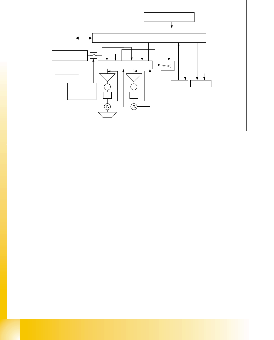
Fig. 11.2 - 1 The interfaces and power supply of the MTC 2 (shown for tower 1)
11.2.1.1 CAN bus
This interface is used for all commands which are sent by the machine controller of the SIPLACE
station. Example: Reference position run and transfer of set-up data.
11.2.1.2 400 V power supply
The MTC 2 is supplied externally with 400 V (USA/Japan: 208/204 V).
11.2.1.3 EMERGENCY STOP interface
The MTC 2 is incorporated in the safety circuit of the SIPLACE station. This provides feedback in
the form of a protective circuit voltage of 24 V. This protective circuit voltage switches the relevant
combination circuit breaker and thus the 400 V of the inverters for the Masterdrives.
The contactors switch off the servo voltage (400 V) and also immediately switch off the power sup-
ply to the brake.
The signaling contact (make contact) of the EMERGENCY STOP button is connected to the input
of the SIPLACE safety signalling system. The break contact interrupts the 24 V protective circuit
voltage of the SIPLACE machine.
If the EMERGENCY STOP circuit in a machine is interrupted (EMERGENCY STOP button), the
Masterdrives of the MTC 2 trip. Both systems are then not under power.
When one of the two protective doors of the MTC 2 is opened, only the control voltage of the rel-
evant tower falls.
24 V supply voltage
C167 Controller board
Servo
M
PI
Servo
M
PI
Brake
CAN bus
Sensors
CAN Bus
Safety
interface
400 V supply
voltage
SIPLACE
Actuators
24 V
24 V
24 V
24 V 24 V
Masterdrive
lifting axis 1
Masterdrive
feed axis 1
Safety
circuit
1
2
3
4

1 - 19
Student Guide SIPLACE HF/HF3
Edition 09/2005 11 MTC 2
19
11.2.2 Reference position run
When the MTC 2 is switched on, a reference position run needs to be performed on the servo
axes, as for the SIPLACE station. If the MTC 2 remains switched on when the SIPLACE station
is switched off and back on, it reports that it has already been referenced.
During the reference position run, both towers move into their reference positions simultaneously.
The two feed axes are moved first and then the two lifting axes.
Each axis first moves to its physical home position then checks the position of the two software
limit switches and finally stops in the software zero position (this corresponds to the relevant zero
offset of the physical home position). The positions adopted by the axes are then defined as ref-
erence and calibration positions.
The reference run for an individual axis is performed as follows:
– The current zero offset is sent to the Masterdrive.
– The controller queries the "neutral position" of the light barrier and waits for a rising edge.
If the axis is already positioned in the light barrier, it issues a "HIGH" signal. The axis moves in
a positive direction until the light barrier delivers a falling edge. The axis then moves in the neg-
ative direction again.
11
If the axis is not positioned in the light barrier, it issues a "LOW" signal. The axis moves in a
negative direction.
11
– The axis moves in the negative direction until the light barrier delivers the necessary rising
edge and the first rotor zero position (index) has been found.
This procedure is necessary, since the zero pulses of the resolver angular encoder are re-
peated with each revolution and thus appear several times within the possible travel range.
– The axes move to both software limit switches in the maximum and minimum positions to within
a few millimeters, to check the saved data.
– Finally, they move to the current zero offset.
NOTE
If the axes are not moved completely to the software limit switches and an error message appears
on the screen for the motor controllers (Masterdrive), one of the axes must be calibrated again.
When the axes have moved to all four reference positions, the SIPLACE station searches for the
two fiducials on the feed axes. The position which is found is used later to define the pick-up po-
sition of components. The fiducials must be available in the MVS file of the line computer.