SG_FSE_SiplaceHF_HF3_00193901-05_eng.pdf - 第486页
1 - 12 S tudent Guide SIPLACE HF/HF3 1 1 MTC 2 Edition 09/2005 12 1 1.1.5.2 Safety instructions for transporting the MTC 2 ➠ The MTC 2 should only be tran sported over any si gnificant distance using a suitable p allet j…
1 - 11
Student Guide SIPLACE HF/HF3
Edition 09/2005 11 MTC 2
11
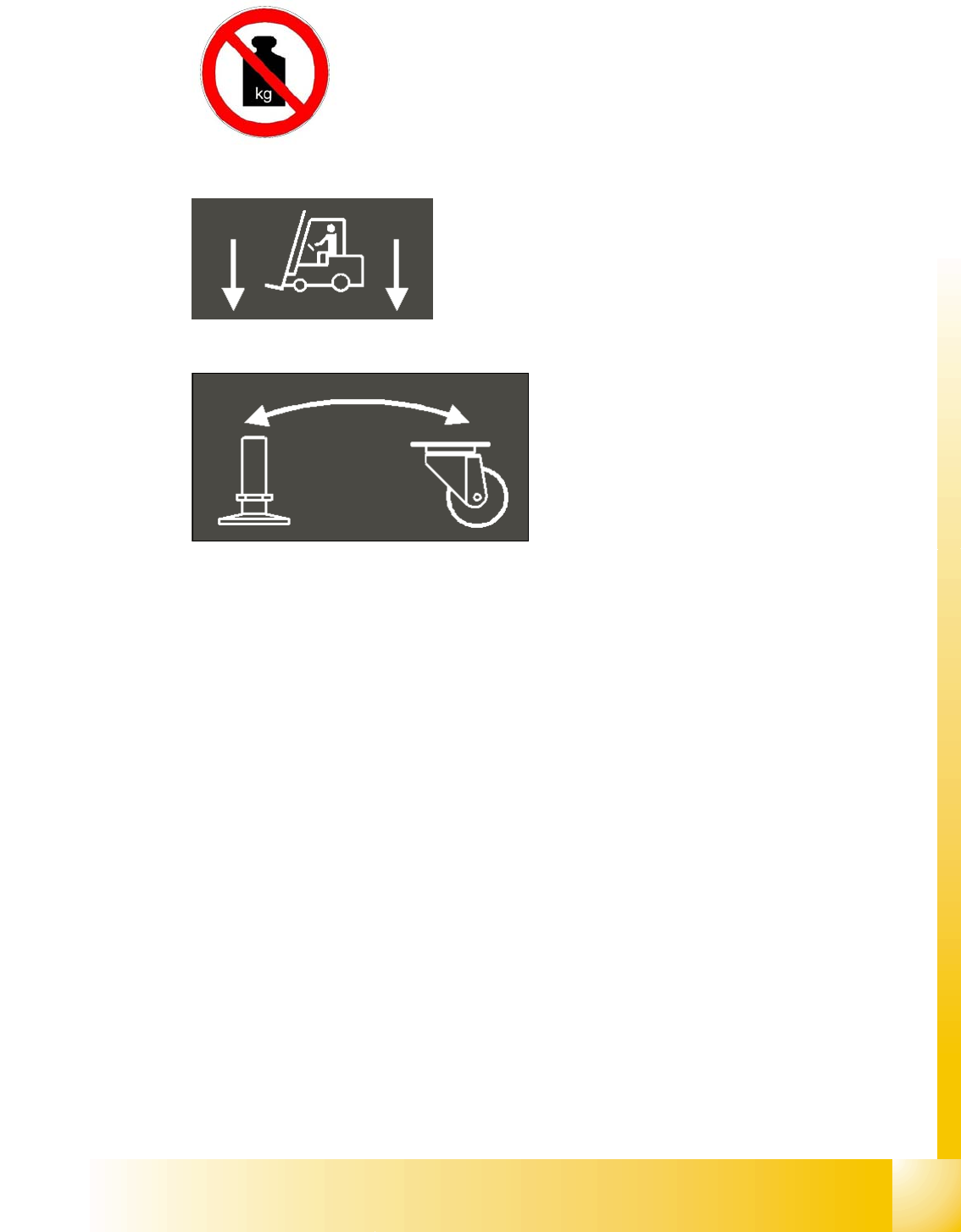
Fig. 11.1 - 14 No loads warning by the feed axis
Fig. 11.1 - 15 Information labels above the guides for the fork lift truck
Fig. 11.1 - 16 Information label for the cranking device
1 - 12
Student Guide SIPLACE HF/HF3
11 MTC 2 Edition 09/2005
12
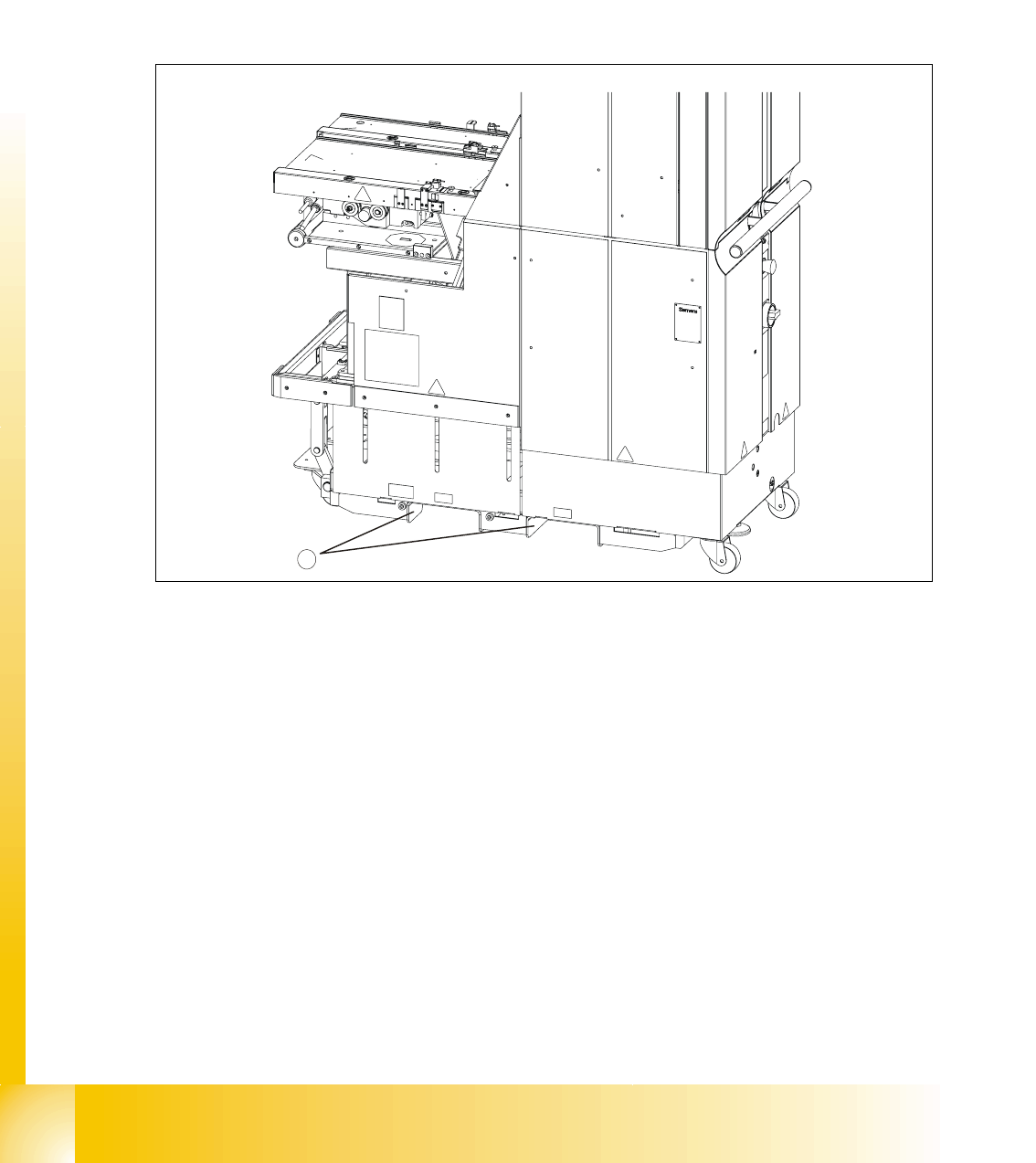
11.1.5.2 Safety instructions for transporting the MTC 2
➠ The MTC 2 should only be transported over any significant distance using a suitable pallet jack
or fork lift truck.
➠ If the fork lift or pallet jack has adjustable forks, the MTC 2 must be lifted at the extremities of
the guide rails.
➠ The forks should only be inserted into the guides from the side on which tower 1 is located.
➠ Follow the instructions in section 3.1 ”Transporting the MTC 2".
Fig. 11.1 - 17 Safety instructions for transporting the MTC 2
Key
1. Guides
11.1.5.3 Residual voltages at the inverters when the MTC 2 is switched off
After switching off the MTC 2
– by pressing the EMERGENCY STOP button,
– by opening a protective door or
– via the SIPLACE station
it takes about 5 minutes before the intermediate-circuit voltages of the inverters have discharged
down to non-hazardous residual voltages.
When the MTC 2 is switched off, the contactor safety combinations continue to be supplied with
24 VAC from the SIPLACE station.
1
1 - 13
Student Guide SIPLACE HF/HF3
Edition 09/2005 11 MTC 2
13
11.1.6 Safety features
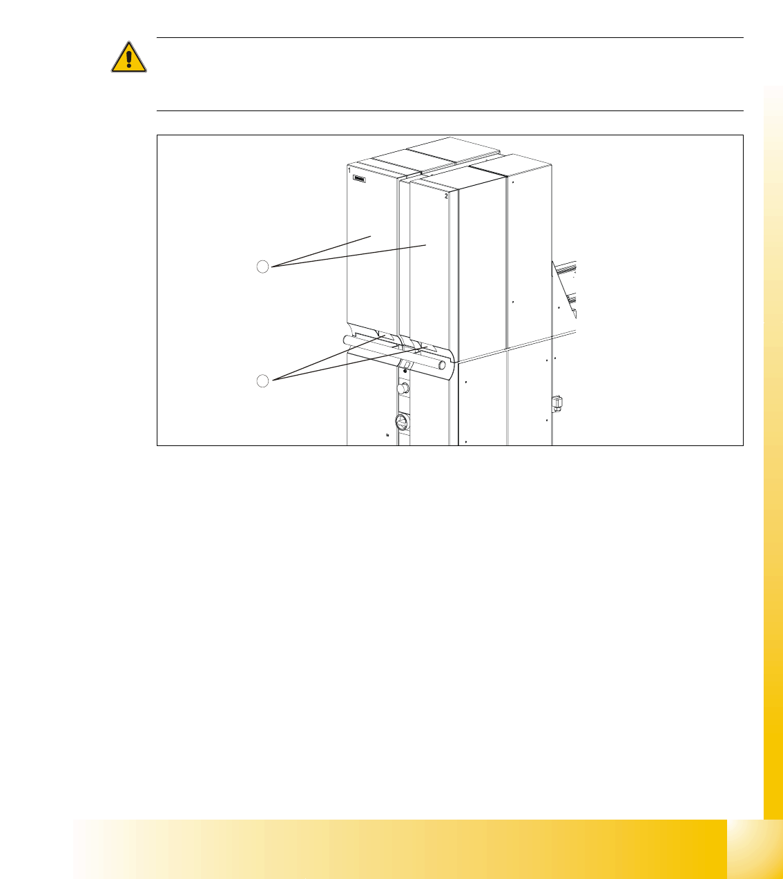
11.1.6.1 Protective doors
Both towers have a protective door. When you open the protective door, the tower is powered
down. The following error message appears: “Tower x: Protective cover not closed”. The other
tower continues to work until it completes its cycle. Once the protective door is closed, the cycle
must be restarted.
CAUTION
Do not open the protective doors of the MTC 2 unless you are informed to do so on the screen of
the station computer or when the MTC 2 has been switched off.
Fig. 11.1 - 18 Protective doors
Key
1. Protective doors
2. Recessed handles
11.1.6.2 EMERGENCY STOP button
The EMERGENCY STOP button is a self-latching combination and designed with bypass protec-
tion according to EN 418. This red, mushroom-shaped button remains depressed when you press
it.
When you press the EMERGENCY STOP button, the entire line with SIPLACE station and MTC
2 is immediately stopped. Placement is interrupted and, once the machine is in working order
again, can be resumed or canceled. Watch out for any incompletely assembled printed circuit
boards.
Pressing the EMERGENCY STOP button opens the two switching contacts of the safety circuits;
1
2