SG_FSE_SiplaceHF_HF3_00193901-05_eng.pdf - 第113页
1 - 43 S tudent Guide SIPLACE HF/HF3 Edition 09/2005 3 Communication and Control 43 3.4.3.1 Servo amplifier TBS .. and SDS ... Fig. 3.4 - 1 1 Servo amplifier This SDS and TBS Servo amplif iers are to reset by Servo disab…
1 - 42
Student Guide SIPLACE HF/HF3
3 Communication and Control Edition 09/2005
42
3.4.3 Axis controller
The Axis controller receives the Target position and Start signal from the MC, all necessary calcu-
lations and controll functions are done on the axis controller.
Fig. 3.4 - 10 View of axis controller board A363 of a HF machine
The Axis controller A 363 are slot coded. This means no address switches have to be set at a
spare part exchange. The Axis controller main board have for each axis type an additional VC 3
controller.
The complete axis control function is done at this Axis controller VC3 controller combination.
Therefor - a BIOs SW
- a Firmware to the Axiscontroller (Application 1) on the Mainboard and
- a Firmware to the VC 3 controller (Application 2)
is loaded.
Because of different types of drives and different control modes this Firmware version may differ
for the axis types. This means the Axis controller can not be swapped very easily to other posi-
tions for different Axis types .
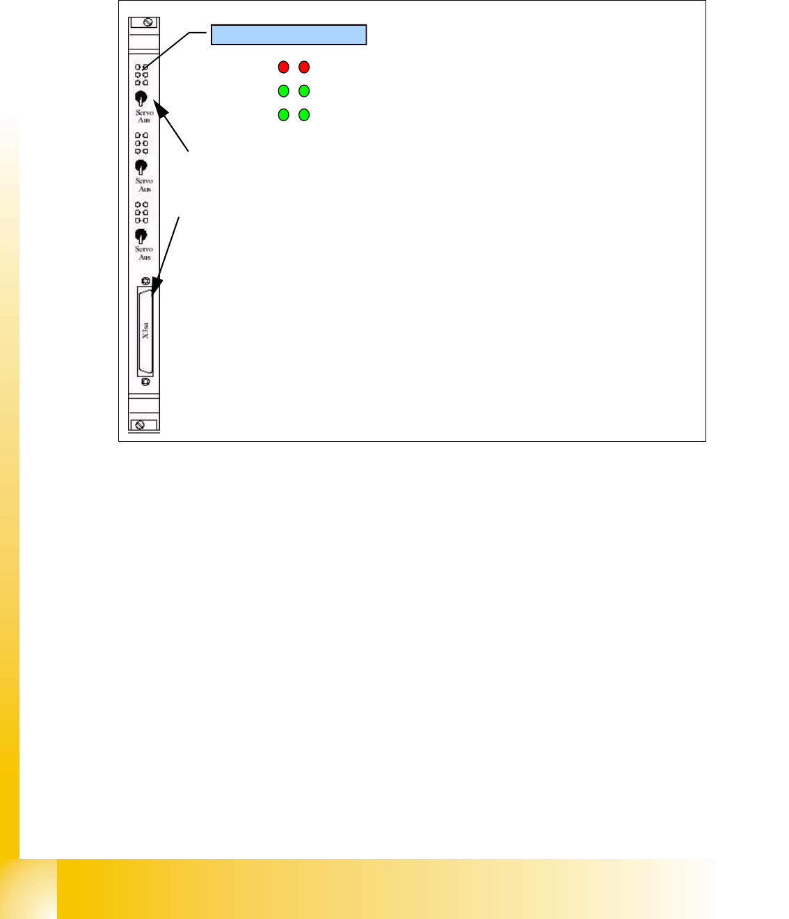
Count error
Inverted
Zero pulse
End signal
Board error
Iinitialized
Servo ON
LED´s state Display
Three Axis controllers on board
Each of them have a manual switch to disable Servo Amplifier.
For each axis controller a few control signals are connected to the front Test connector.
(track A/B/Zero pulse / Start/actual pos. is nominal pos./endsignal/uncom.nom.current
/ Vnominal/Force)
1 - 43
Student Guide SIPLACE HF/HF3
Edition 09/2005 3 Communication and Control
43
3.4.3.1 Servo amplifier TBS .. and SDS ...
Fig. 3.4 - 11 Servo amplifier
This SDS and TBS Servo amplifiers are to reset by Servo disable / Servo enable at Axis controller
board.
All Servos special adjusted to the maximum current of the drive motor of the refering axis type.
This mean the servo amplifiers have to be mount axis specifically.
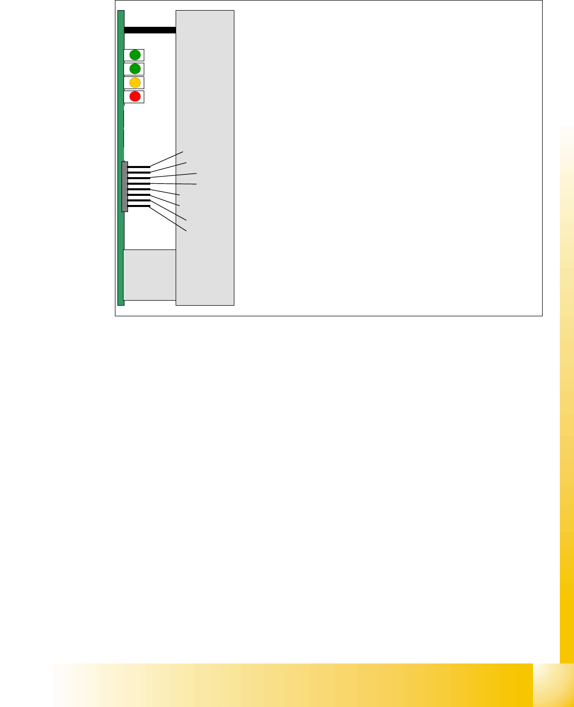
Nominal current I
U
Nominal current I
W
Actual current I
U
Actual current I
W
Outp. Current controller Voltage V
U
Outp. Current controller Voltage V
W
Error
GND
Ready
Servo Enable
I
RMS
error
Board error
The nominal current signals also measurable at V nominal / Force
output of Axis controller
The Pin 3/4 show the actual current signals to the motor.
This signals are 180° phaseshifted to the nominal signal.
The Pin 5/6 show the voltages to drive the sinusoidal current
Ready is ON when Machine is ON
Servo Enable is first activated with a start of reference run. At X/Y
axis it is disabled after 2 min. without action and at Service posi-
tion.
I RMS error light up at short over current pulses.
Board error is a ’permanent’ error like over voltage / over current /
over temperature.