SG_FSE_SiplaceHF_HF3_00193901-05_eng.pdf - 第354页
1 - 6 S tudent Guide SIPLACE HF/HF3 7 TWIN-Head Edition 09/2005 6 7.6.1.1 Overview positioning time for the TWIN- head 7 Please Note: (Z-Axis) The positionin g time for the Z -axis with the current mode and force se nsor…
1 - 5
Student Guide SIPLACE HF/HF3
Edition 09/2005 7 TWIN-Head
5
7.6 Axis control
7.6.1 Overview Axis control Z- and D-Axis
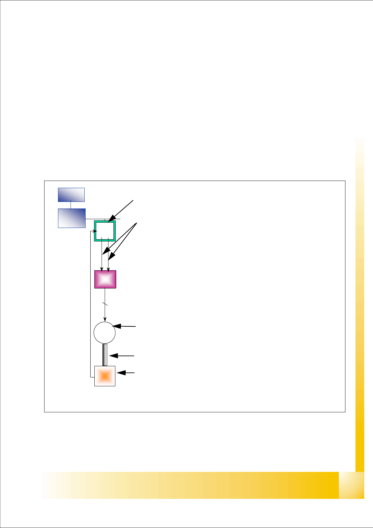
The closed-loop control system for control of the head axes consists of the following parts.
– Axis controller with VC 3 Controller
– Servo card (SDS)
– Motor
– Measuring system (Incremental- scale and -encoder)
Between the head axes, some differences which will be explain later in this chapter.
Fig. 7.6 - 1 Example: Axis control D-axis
MC
COM
board
VC 3
cont
Servo
ampli.
M
2 ~
Enco-
der
2
Axis card A363 with VC 3 Controller (VC = Velocity Commutation)
Control signals I
nom "W" and I nom "U"
LED‘s on the Servo amplifier:
– Power supply ON
– Servo enable, if the the enable signal from the axis board available.
– Display RMS current limiter shorter than 2,5 s.
– Error: Overvoltage, -current, -temperature or Nominal current-overstep-
ping longer than 2,5 sec.
Servo board control directly the motor.
2 Phase AC motor for D Axis.
3 phase AC linear motor for Z-Axis
Between the motor and the incremental encoder exist a fixed mechanical
combination.
Incremental encoder: trace the exact position of the axis via track signal.
1 - 6
Student Guide SIPLACE HF/HF3
7 TWIN-Head Edition 09/2005
6
7.6.1.1 Overview positioning time for the TWIN- head
7
Please Note: (Z-Axis)
The positioning time for the Z-axis with the current mode and force sensor have no direct inference
to the function.
In order to check this functions please use an oscilloscope and for the mode force sensor a special
PCB board with force sensor. 7
Please Note: (D-Axis)
The positioning time for the left and right rotation of the D-axis could be a little bit different, but this
time is not critical in case of the placement sequence of the TWIN- head. 7
Axis Mode / Distance / Positioning time
Z Positioning absolut,
free space /
Distance 100000 digits = 50000 µm
(Resolution 0,5µm)
84ms +/-3ms
Z Current mode (to measure force)
into calibration tool pocket,
518 nozzle
Distance 92000 digits =46000 µm,
force 2N
ca. 240ms *
*see note below
Z Force sensor (o measure force)
into calibration tool pocket,
518 nozzle
Distance 46000 µm,
force 13N
ca. 240ms *
*see note below
D 10000 digits = 10 degree 90ms +/-10ms*
*see note below
D 90000 digits = 90 degree 150ms +/-20ms*
*see note below
D 180000 digits = 180 degree 190ms +/-20ms*
*see note below
Table 7.6 - 1 Positioning time for TWIN- head
1 - 7
Student Guide SIPLACE HF/HF3
Edition 09/2005 7 TWIN-Head
7
7.6.2 Track signals head axes
The track signals undertake the main control function in the case of the new drive concept of the
HF machine. They are responsible for the exact and precise positioning of the axes and are used
as only response of the closed-loop control system so that the track signals have an important
influence on dynamics of the axes.
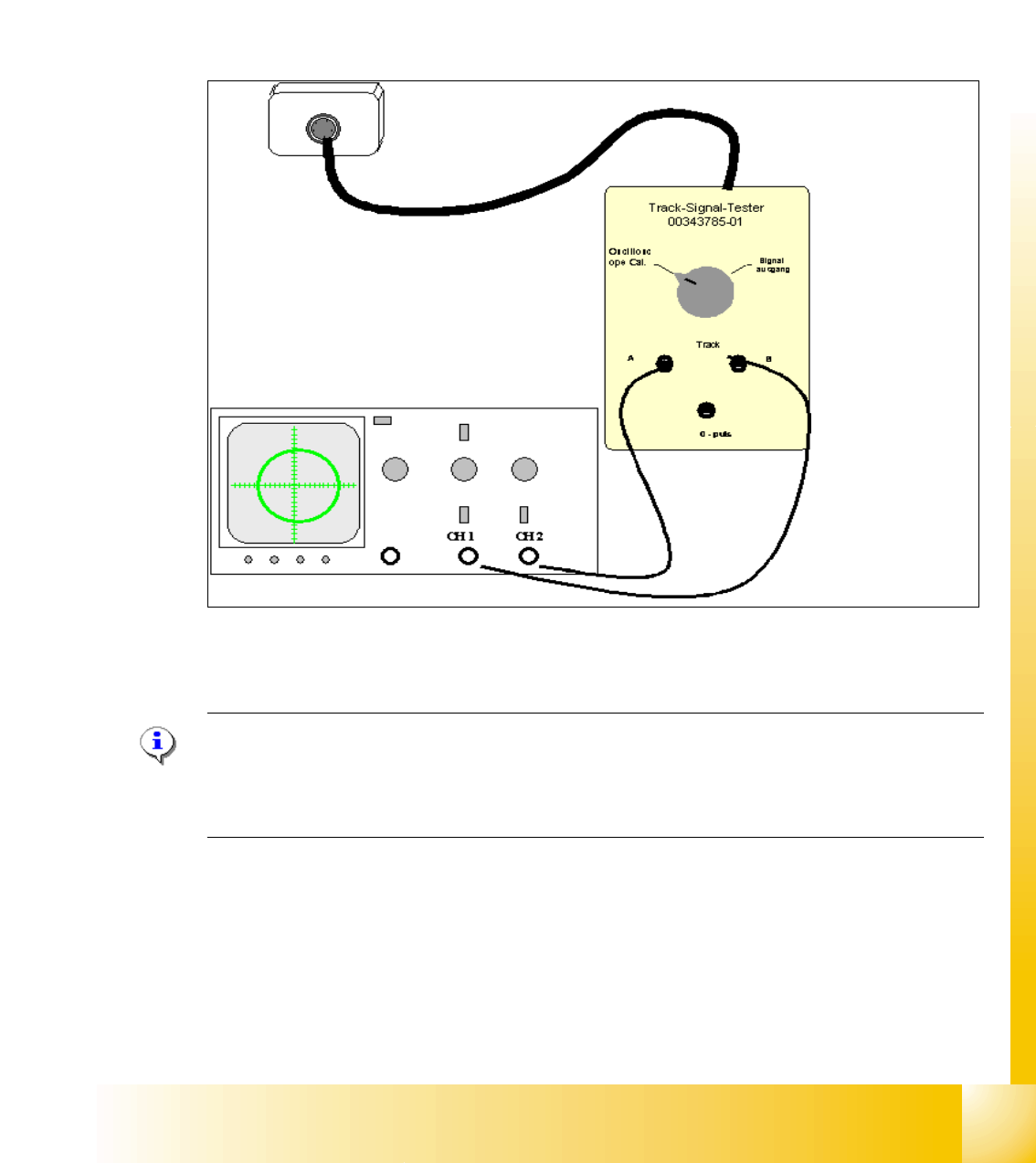
7.6.2.1 Test set up
Fig. 7.6 - 2 General test set up to check the analoge track signals TWIN- Z-axis
The analoge track signals of the TWIN- head Z-axes are measurable on the incremental encoder.
Please Note:
The digital track signals of the TWIN- head can only be measured on the axis test box.
The track signals of theTWIN head D-axes can only be measured as digital signals on the axis
test box. 7