SG_FSE_SiplaceHF_HF3_00193901-05_eng.pdf - 第335页
1 - 23 S tudent Guide SIPLACE HF/HF3 Edition 09/2005 7 TWIN-Head 23 7.4.1.4 Head adapter T win Head The head adapter boar d connect s the head interface board dir ectly to the main board of T win head segment 1 and 2 via…
1 - 22
Student Guide SIPLACE HF/HF3
7 TWIN-Head Edition 09/2005
22
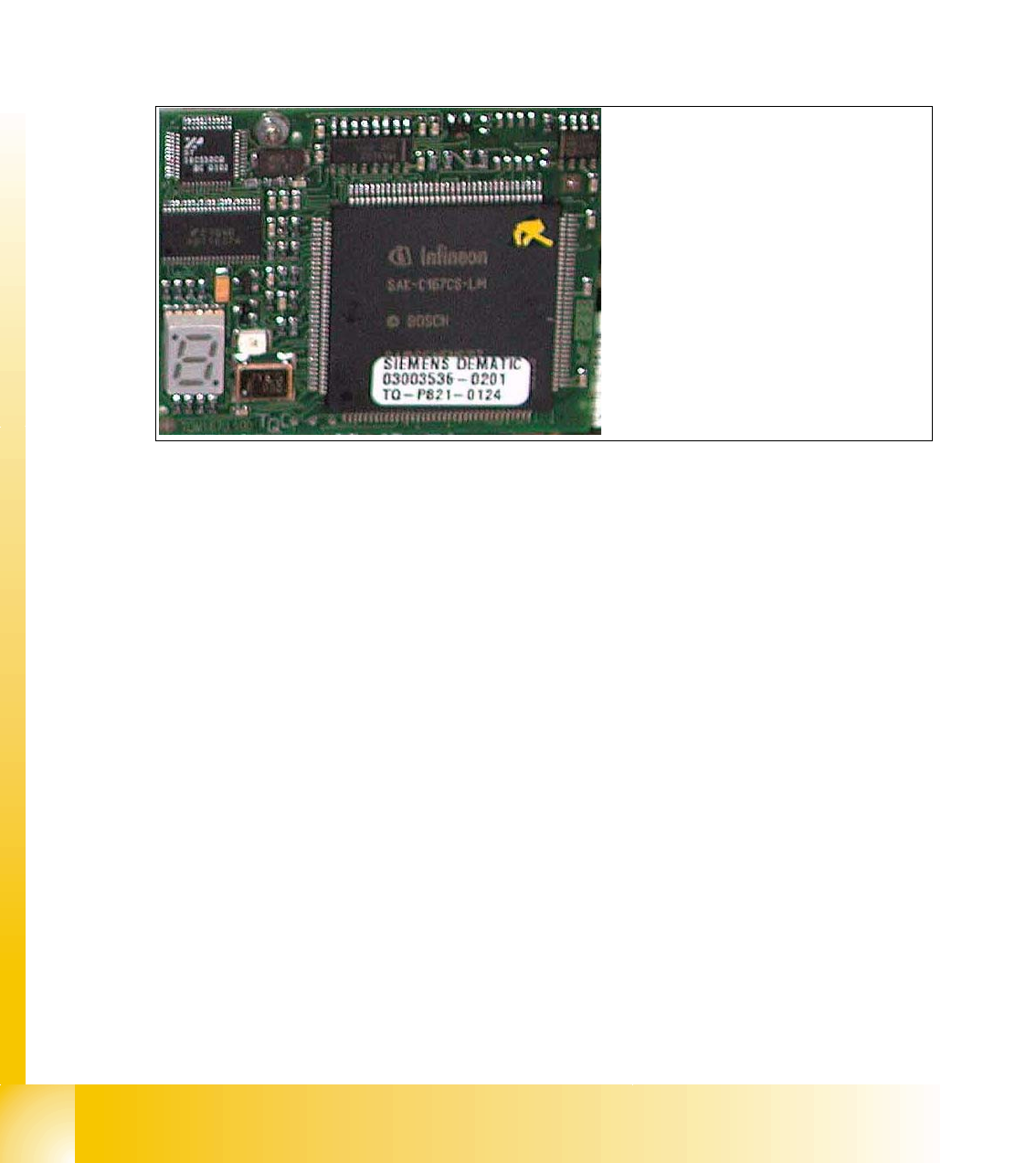
7.4.1.3 CAN Processorboard 16 Bit
The 16 BIT CAN Processor is used for different functions of the following units:
– Visionboard, Communication and control via the ICOS system
– Mainboard Twin head, control the Vacuum generator
– Visionboard for the stationary IC (FC) - Camera, communication and control via the ICOS
system
Abb. 7.4 - 3 16 Bit Processor
Description 7 Segment display ( Standard mode " . " flashed):
– After switch ON the machine " 0 " appears on the display
– Display " b " Bios is started.
– Display flash alternately "b" and " . " --> none Application available or can not started.
– Display " -I " und " I- " Application is loaded and now starts.
– The " . " on the display flashed.
(1) 7 Segment display
(2) LED red at the bei manual RESET
on the Processors
(3) 16 Bit Processor
2
3
1
1 - 23
Student Guide SIPLACE HF/HF3
Edition 09/2005 7 TWIN-Head
23
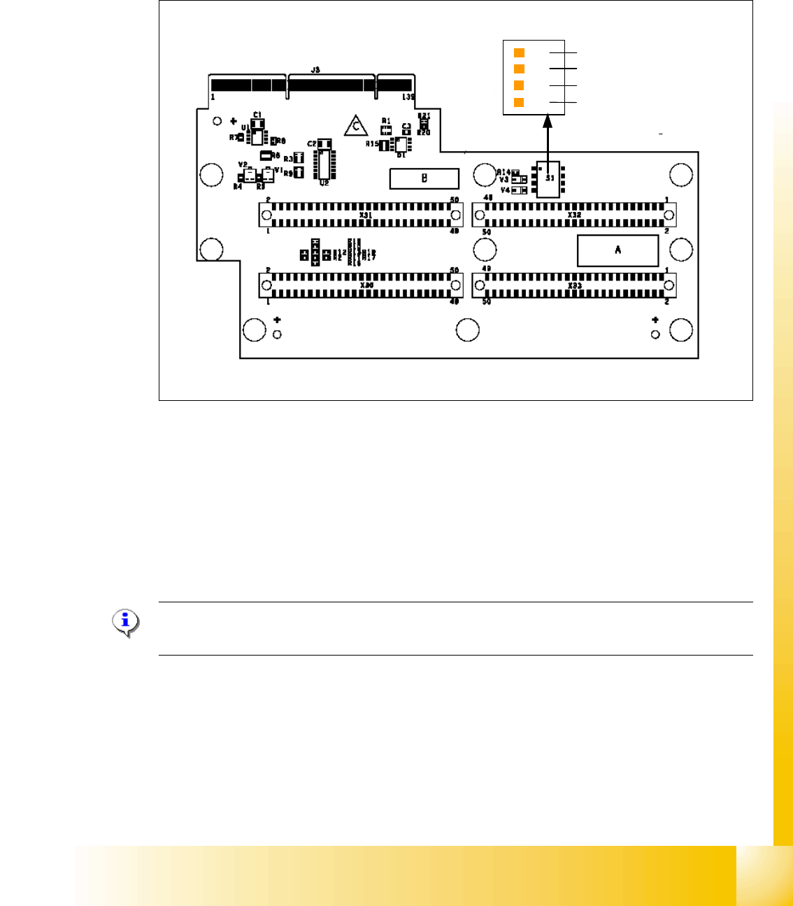
7.4.1.4 Head adapter Twin Head
The head adapter board connects the head interface board directly to the main board of Twin head
segment 1 and 2 via ribbon cable. This head adapter must be changed for head modularity, if you
use a C&P head.
Fig. 7.4 - 4 Head adapter Twin head
Please Note:
The ribbon cable sets for the Twin head segment 1and 2 are different.
(1) Connector Z-Axis Twin head 1 (2) Connector D-Axis Twin head 1
(3) Connector DP-Axis Twin head 2 (4) Connector Z-Axis Twin head 2
(5) PP1 Boot CAN Processor Twin Segm. 1 (6) PP1 Reset CAN Processor Twin Segm. 1
(7) PP2 Boot CAN Processor Twin Segm. 2 (8) PP2 Reset CAN Processor Twin Segm. 2
1
24
3
OFF
1
4
5
6
7
8
1 - 24
Student Guide SIPLACE HF/HF3
7 TWIN-Head Edition 09/2005
24
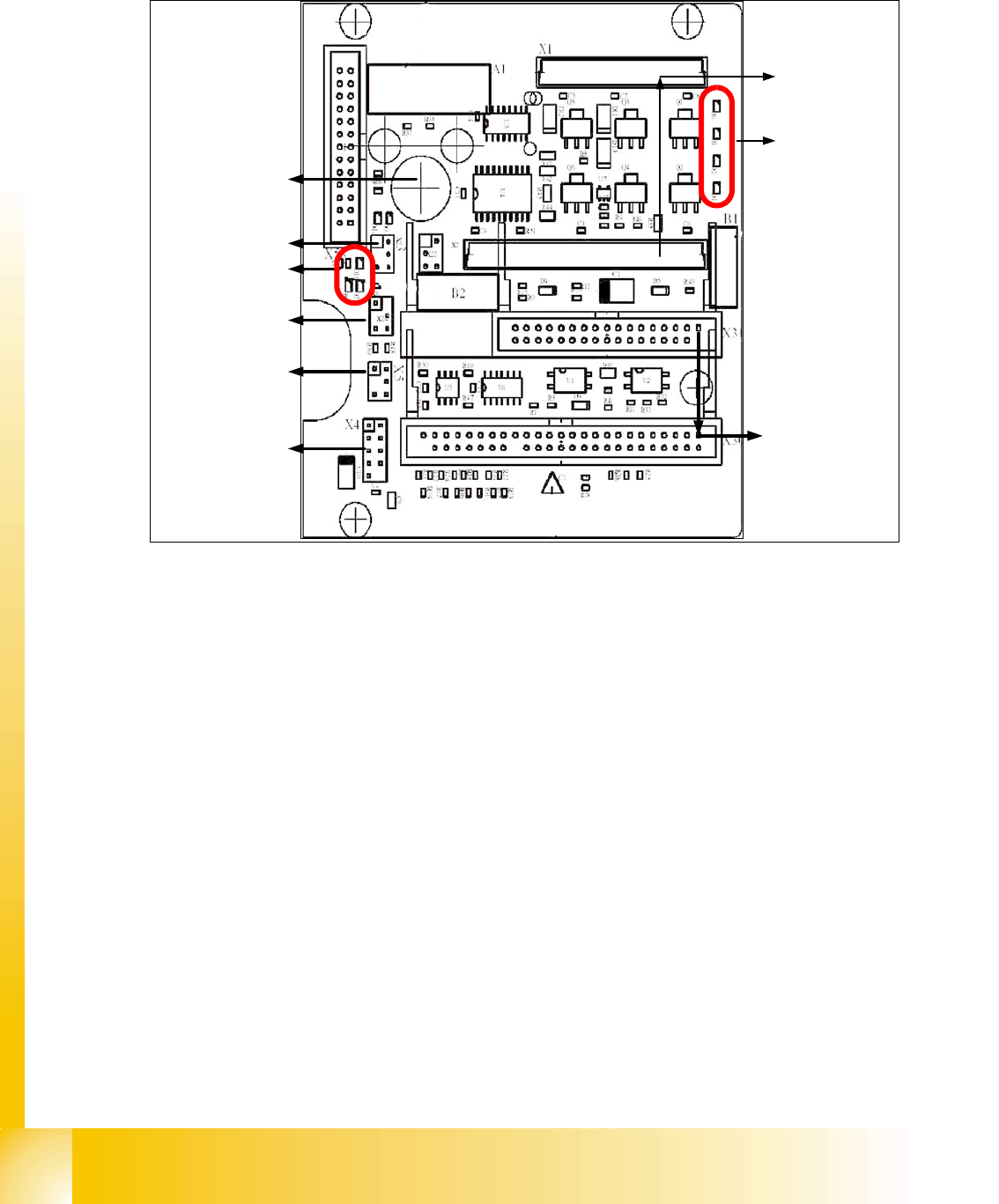
7.4.1.5 TWIN-Head main board
The main board is mounted directly on the top of the frame of the TWIN-head. This board is con-
nected to the head adapter via ribbon cable (one ribbon cable for each axis).
Fig. 7.4 - 5 Main board at TWIN-head segment
1. Connector for the 16 Bit CAN Bus Processor (Control the analog or digital vacuumgenerator)
2. LED´S (Description from top to bottom)
- D6 BERO Z-axis top (not used)
- D1 not defined
- D2 Clamping Z-axis (yellow) LED off, retract unit is at top position.
- D15 Temperature monitoring Z-axis linear motor (red) LED on, is ok.
3. Connectors to the head adapter
4. Connector track signals Z-axis
5. Connector BERO Z-axis (not used)
6. Connector pneumatic valve (retract unit)
7. LED‘s: D7- is ON after reference run
D8- protect Z-axis without function
D9 - without function
D10 - green LED ON 24Vfor the vacuumgenerator
D14 - Alarm output for the vacuumgenerator ( red LED ON vacuumgenerator defect)
8. Connector for valve (only 24 Volts on pin 2 and 4 measured)
9. Hole for pneumatic pipe to the vacuum generator
1
2
3
4
6
5
7
8
9