SG_FSE_SiplaceHF_HF3_00193901-05_eng.pdf - 第302页
1 - 102 S tudent Guide SIPLACE HF/HF3 6 Collect &Place-He ad / DLM2 Edition 09/2005 102 6.7.7 H ead modularity C & P Head to T win Head 6.7.8 H ead modularity T win Head to C&P Head 1. Data b a ckup(see 8.5.3…
1 - 101
Student Guide SIPLACE HF/HF3
Edition 09/2005 6 Collect &Place-Head / DLM2
101
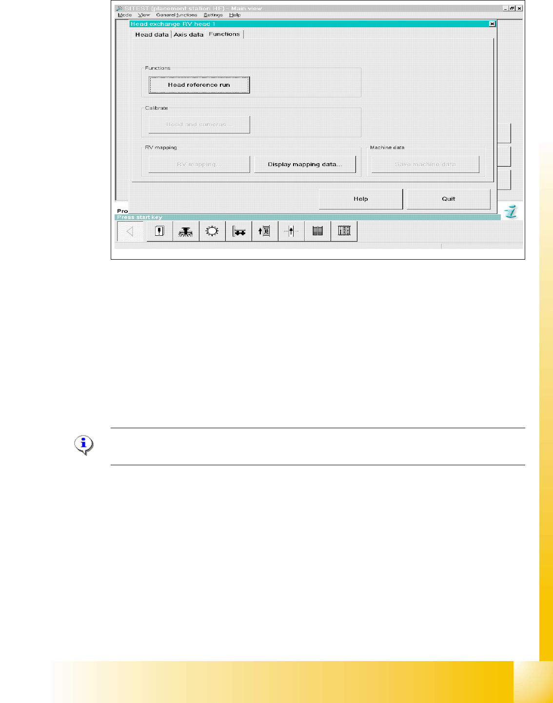
Fig. 6.7 - 7 Menu "Head exchange" --> "Functions
(1) Head reference run to check the function and for calibration reference run the whole machine.
(2) Link to calibrate head and cameras.
(3) Mapping menu
(4) Display mapping data
(5) Link to machine data
6.7.6 Calibration
Please Note:
See Chapter Sitest "Calibration".
HF / HF3 C&P 6
➠ Calibrate zero point correction both gantries.
➠ Calibrate PCB camera
➠ Calibrate C&P head
➠ Component camera
➠ Segment offset 2
➠ Segment offset 1
➠ Calibrate nozzlechanger (inclusive automatic pick up height)
4
1
2
3
5
1 - 102
Student Guide SIPLACE HF/HF3
6 Collect &Place-Head / DLM2 Edition 09/2005
102
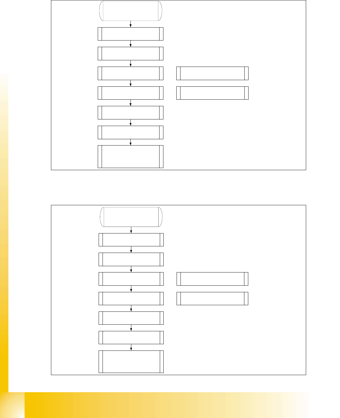
6.7.7 Head modularity C&P Head to Twin Head
6.7.8 Head modularity Twin Head to C&P Head
1. Data backup(see 8.5.3).
2. Remove C&P head with head
adapter.
3. Remove nozzle changer for C&P
head.
4. Mount stationary IC and/or FC-
camera.
Note: Twin head not possible in
placement areas with two gantries.
5. Mount Twin head with head
adapter.
6. Mount nozzle changer Twin
head at location 1.
7. Calibrate Twin head and
cameras.
8. With increase placement
accuracy carring out the fine
calibrationen.
Note: Check the DIP -Switches.
Change the grub screws into the
correct position.
1. Data backup(see 8.5.3).
2. Remove Twin head with head
adapter.
3. Remove nozzle changer for Twin
head.
4. Remove the stationary IC and/or
FC- camera.
Note: Remove the camera
"HEADCRASH".
5. Mount C&P head with head
adapter.
6. Mount the nozzle changer C&P
head at location 1.
7. Calibrate C&P head and
cameras.
8. With increase placement
accuracy carring out the fine
calibrationen.
Note: Check the DIP -Switches.

1 - 103
Student Guide SIPLACE HF/HF3
Edition 09/2005 6 Collect &Place-Head / DLM2
103
6.8 DLM 2 C&P Head HS-60 / S-27 HM and HF machine
6.8.1 Overview DLM 1 versus DLM 2 C&P Head
The DLM 2 C&P Head is a further development of the DLM 1 C&P Head.
The DLM 2 C&P Head comes into operation on the SIPLACE HS-60 and S-27 HM together with
the software version 503 - furthermore on the SIPLACE HF together with software version 504.
Please Note:
The application of the DLM 2 C&P Head requires a modular head PCB. The modular head PCB
is required for the control of the valve drives and the operation of the multi-color camera compo-
nent-sensor (0201-placement).
.
Description DLM 1 DLM 2 Advantages
Head assembly
new front and back plate
(grip, mounting of star
motor, mounting of
turning station)
more robust against
vibrations and
oscillations
Head mounting 3 screws 4 screws
more robust against
vibrations and
oscillations
Head cover
head PCB on top,
head right and left side
and front
Less Pollution, higher
ESD-safety
Mounting of head PCB new bracket
more robust against
vibrations and
oscillations
Mounting of X-axis encoder new mount
more robust against
vibrations and
oscillations
Z-axis guidance advanced guidance higher durability
New star brake
rettrofit on
HS55
standard on all DLM2
heads
stabalizes star axis dyna-
mic
Shaft star motor diameter 15mm higher durability
Track signal resolution (on star mo-
tor)
10x: at S-27
HM, HS 60 25x: at HF’s
Modular application of
C&Phead
Attachment point of valve drive for
rejection cycle
relocated upwardly by
15°
more free space between
component and PCB
Table 6.8 - 1 Differences between DLM 1 and DLM 2 Heads