SG_FSE_SiplaceHF_HF3_00193901-05_eng.pdf - 第79页
1 - 9 S tudent Guide SIPLACE HF/HF3 Edition 09/2005 3 Communication and Control 9 3.3 CAN Bus 3.3.1 History of CAN The development of CAN began when more and more electronic devices were implemented into modern motor veh…
1 - 8
Student Guide SIPLACE HF/HF3
3 Communication and Control Edition 09/2005
8
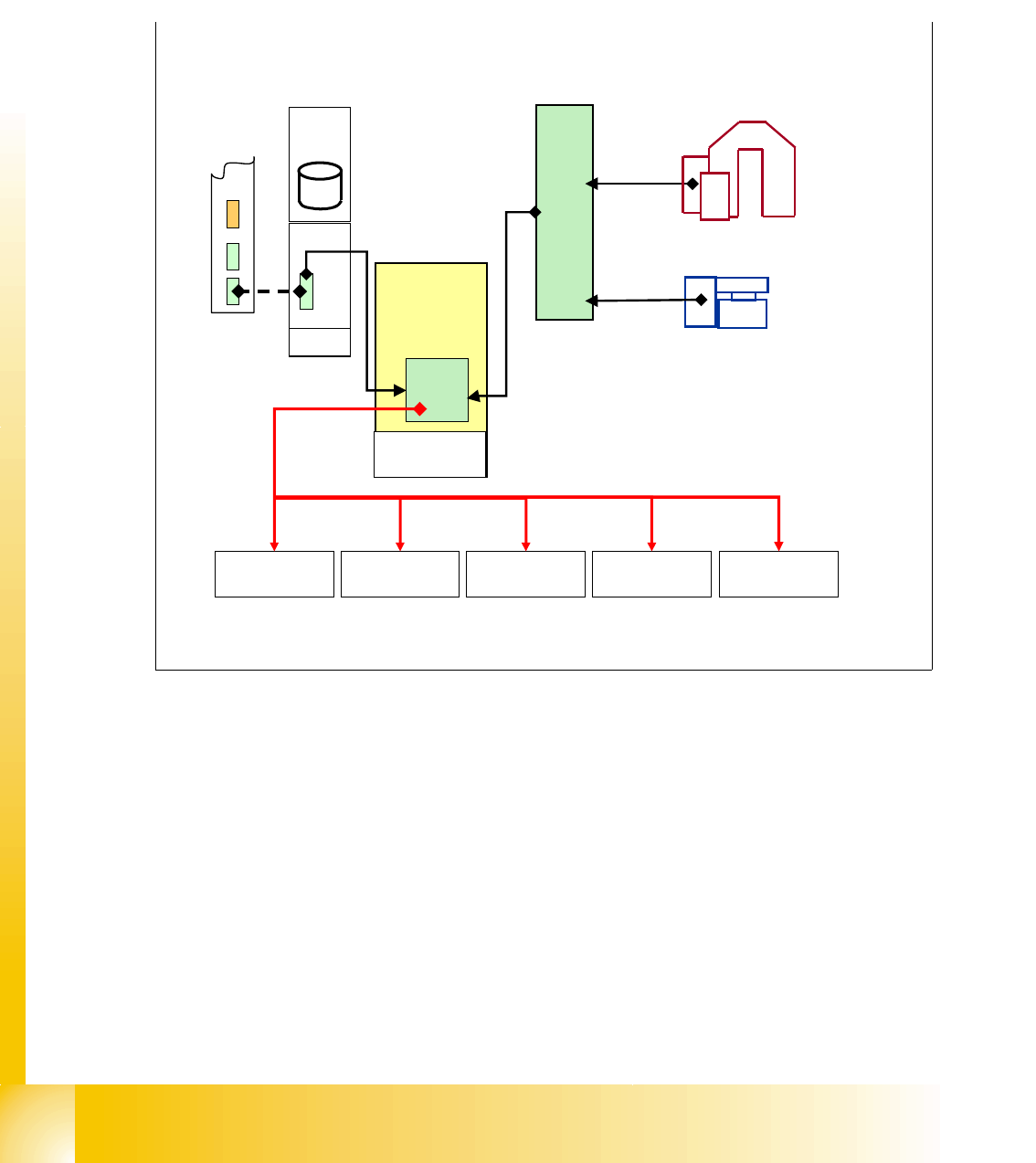
3.2.3 Machine Controller Communication
For the calculation of the ’pick up coordinates’ the MC add the pick up correction values (former
pick up offsets) to the pick up coordinates.
For the calculation of the
’placement coordinates’ the MC add the PCB position correction values
and the component correction values (from camera evaluation) to the placement coordinates.
Fig. 3.2 - 4 communication with MC
X-Axis
controller
SC
MVS
340
Machine
Controller
Y-Axis
controller
Star-Axis
controller
Z-Axis
controller
DP-Axis
controller
Placement
data at MC
+
target position for
pick-up / placement to axis
controller from MC
1 - 9
Student Guide SIPLACE HF/HF3
Edition 09/2005 3 Communication and Control
9
3.3 CAN Bus
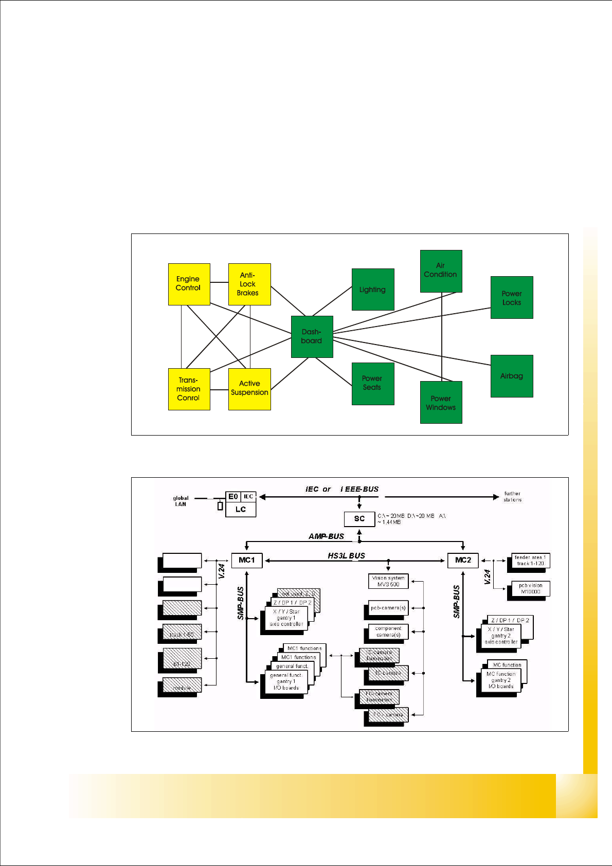
3.3.1 History of CAN
The development of CAN began when more and more electronic devices were implemented into
modern motor vehicles. Examples of such devices include engine management systems, active
suspension, ABS, gear control, lighting control, air conditioning, airbags and central locking. All
this means more safety and more comfort for the driver and of course a reduction of fuel consump-
tion and exhaust emissions.
Fig. 3.3 - 1 communication via cable connection
Fig. 3.3 - 2 communication e.g. on Siplace S15 machine
1 - 10
Student Guide SIPLACE HF/HF3
3 Communication and Control Edition 09/2005
10
To improve the behavior of the vehicle even further, it was necessary for the different control sys-
tems (and their sensors) to exchange information. This was usually done by discrete interconnec-
tion of the different systems (i.e. point to point wiring). The requirement for information exchange
has then grown to such an extent that a cable network with a length of up to several miles and
many connectors was required. This produced growing problems concerning material cost, pro-
duction time and reliability.
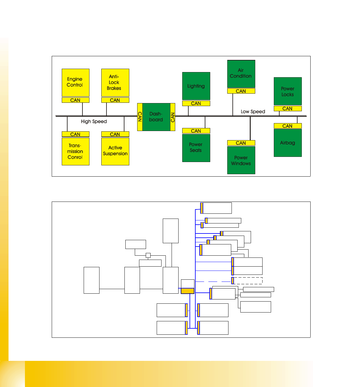
The solution to this problem was the connection of the control systems via a serial bus system.
This bus had to fulfill some special requirements due to its usage in a vehicle. With the use of CAN,
point-to-point wiring is replaced by one serial bus connecting all control systems. This is accom-
plished by adding some CAN-specific hardware to each control unit that provides the ’rules’ or pro-
tocol for transmitting and receiving information via the bus.
Fig. 3.3 - 3 Communication via CAN bus on example car controlling
Fig. 3.3 - 4 CAN communication on SIPLACE HF
I/O Slio Board (SUB)
Transport
control
camera Illumination
control Board
Head Board gantry 3
Axis controller Board
Axis controller Board
Axis controller Board
I/O Slio Board (Main)
Line
computer
Station
computer
Machine
controller
LAN
Vision
system
MVS 100
H S
3
L Bus
Axis controller Board
Comp. table
controller
CAN Bus
Comp. table
controller
Comp.
Barcode
Transport
control
communi
cation
board
LAN
Comp. table
controller
Comp. table
controller
TSP 1 actors
PCB-Barcode
Keyboard
camera Illumination
control Board
Head Board gantry 1
TSP 2 actors