SG_FSE_SiplaceHF_HF3_00193901-05_eng.pdf - 第418页
1 - 32 S tudent Guide SIPLACE HF/HF3 9 Modular convey or Edition 09/2005 32 ➠ Choose the lifting table which you would check and press the bu tton UP and DOWN . 1. The time for up and down appears in fro nt of the button…
1 - 31
Student Guide SIPLACE HF/HF3
Edition 09/2005 9 Modular conveyor
31
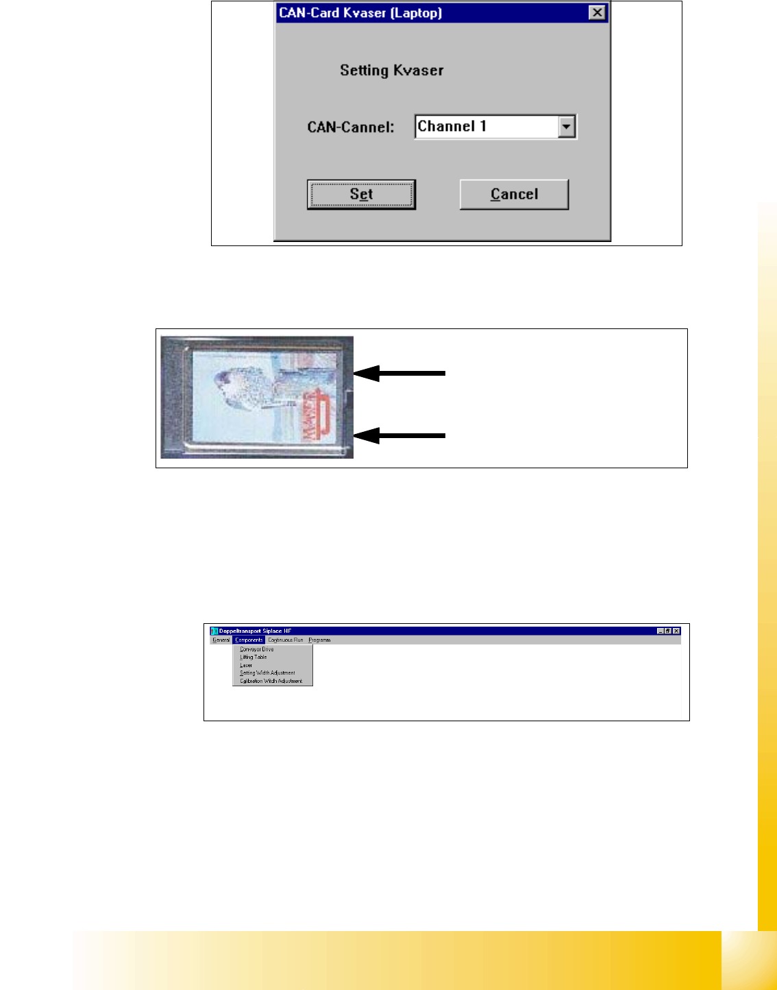
➠ Select the cannel which you use on the Kvaser card (Cannel 1 or 2)
Fig. 9.2 - 20 Connections of the Kvaser Card
➠ Confirm this settings with "Set".
➠ Following Message appears "Settings undertaken" .
➠ Click "OK".
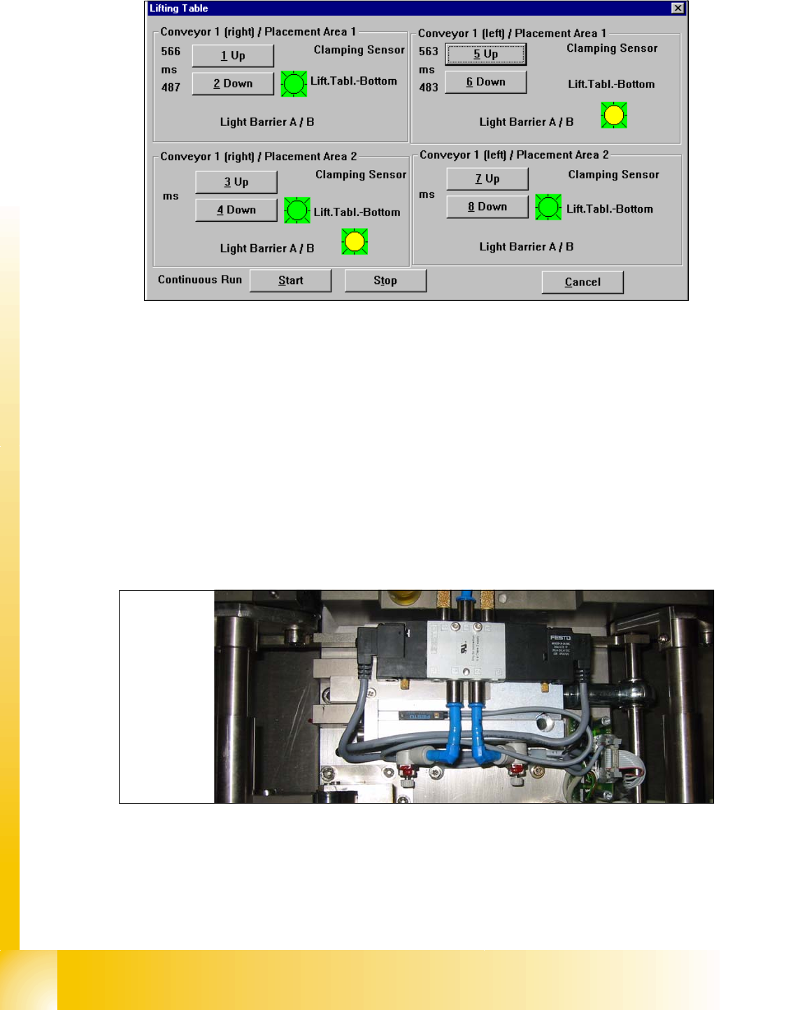
➠ Select in the upper menue "Components" the lifting table
➠ Following Windows appears
Precondition: 9
– Machine is switch on
– Cover closed
– Control ON
Cannel 2
Cannel 1
1 - 32
Student Guide SIPLACE HF/HF3
9 Modular conveyor Edition 09/2005
32
➠ Choose the lifting table which you would check and press the button UP and DOWN.
1. The time for up and down appears in front of the button.
2. If the lifting table move up appears a red light for a short time.
3. Sign (LED on the pneumatic cylinder)for move down the lifting table
4. Sign for move up the lifting table. (Incremental encoder--> Number of the steps were counted
correct)
➠ Adjust the valve on the lifting table cylinder, so that you get the following values:
– Lifting table up: 500 +/- 20ms (
~450 +/-20ms DT / ~360 +/-20 ms ST without lifting table plate)
– Lifting table down: 480 +/- 20ms (
~360 +/-20ms DT / ~ 600 +/-20ms ST without lifting table plate)
➠ Set the lowering speed according the processing needs of your placed PCB.
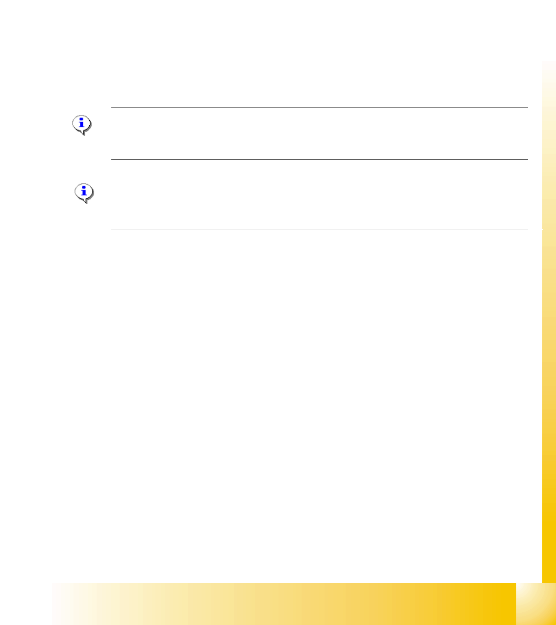
(1)Cylinder drive rod (2) 3/5 solenoid
(3) adjust valve downwards (4) adjust valve upwards
Setting valve anticlockwise: Decrease the lifting table moving time
Setting valve clockwise: Increases the lifting table moving time
1
2
3
4
(2)
(4)
(3)
(1)
1 - 33
Student Guide SIPLACE HF/HF3
Edition 09/2005 9 Modular conveyor
33
9.2.12 Checks after mechanical work on the conveyor
1. Check: Distance between the top edge of the conveyor belt and the top stop.
This value should be
6 mm .
2. Check: Distance between the top edge of the conveyor belt and the top stop, at the clamping
sensor.
This value should be
5.8 mm.
3. Check: Distance between clamping actuator (lifting table) and top edge of the belt.
This value should be
94.2 mm on the HF and HS-60.
4. Check: Distance between clamping actuator (lifting table) and top edge of belt at the clamping
sensor.
This value should be
94.4 mm on the HF and HS-60.
Note for machine with clamping sensor:
The actuator must be seated 0.2 - 0.3 mm deeper below the clamping sensor to ensure that the
piezo sensor (force sensor) is triggered reliably.
Please Note: for machine without clamping sensor:
The distance between clamping actuator (lifting table) and top edge of the belt should be on all
four positions 94,0mm.