SG_FSE_SiplaceHF_HF3_00193901-05_eng.pdf - 第90页
1 - 20 S tudent Guide SIPLACE HF/HF3 3 Communication and Control Edition 09/2005 20 3.3.8 CAN Bus Processor Board T win Head CAN: bus processor board is using a 16 b it microcontroller Fig. 3.3 - 17 16 bit CAN Bus proces…
1 - 19
Student Guide SIPLACE HF/HF3
Edition 09/2005 3 Communication and Control
19
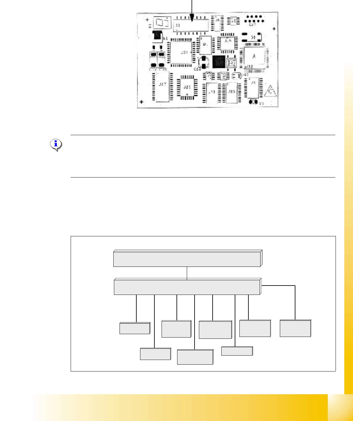
3.3.7 CAN Bus Processor Board C&P Head
CAN: bus processor board is using a 8 bit microcontroller
Fig. 3.3 - 15 8 bit Processor Board C&P Head
NOTE:
The status of the PROCESSOR BOARD 80C515C FW is indicated on the 7-segment display.
Normal status on the diplay is: Display shows " 0 " and the " . " flashed slowly
(Description of the 7-segment display see chapter C&P Head).
3.3.7.1 CAN Bus controlled function on C&P Head
The following overview shows various head functions, controlled by the CAN system. Thus, the
CAN bus controls the actuators and sensors of the C&P Head.
Fig. 3.3 - 16 CAN function on C&P Head
Co-sensor
CAN Bus 8 bit Processor Board
stepper motor
reject
:
LS top
LS bottom solenoid valve
air kiss
:
CAN bus
stepper motor
swivel in Dp
stepper motor
pick up / place
Vacuum values
Communication Board
1 - 20
Student Guide SIPLACE HF/HF3
3 Communication and Control Edition 09/2005
20
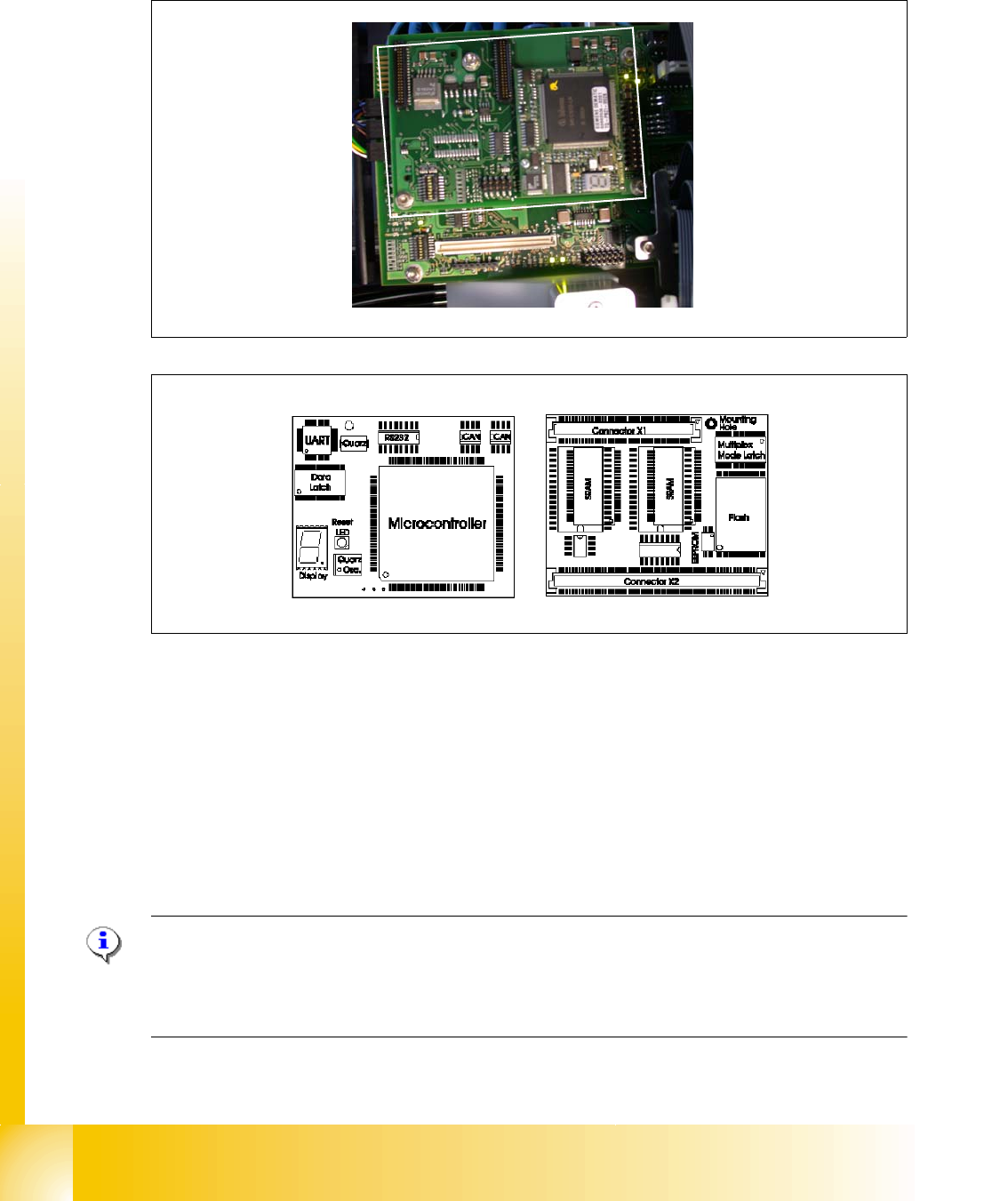
3.3.8 CAN Bus Processor Board Twin Head
CAN: bus processor board is using a 16 bit microcontroller
Fig. 3.3 - 17 16 bit CAN Bus processor board Twin head
Legend:
NOTE:
The status of the 16 bit PROCESSOR BOARD is indicated on the 7-segment display.
Normal status on the diplay is: " . " flashed
(Description of the 7-segment display see chapter C&P Head).
(1) 16 Bit micro controller (2) CAN: driver
(3) 7 segment display (see chapter 8) (4) Reset LED
(5) Crystal oscillator (quarz), for processor
frequency
(6) flash memory
(7) SRAM
2
1
4
5
3
6
7
1 - 21
Student Guide SIPLACE HF/HF3
Edition 09/2005 3 Communication and Control
21
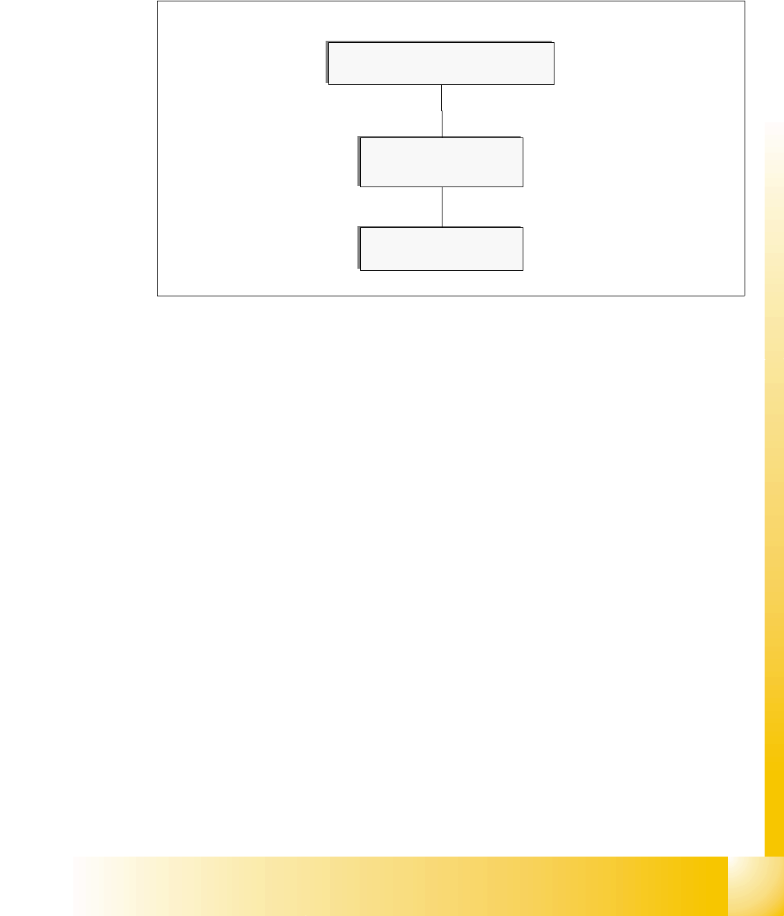
3.3.8.1 CAN bus controlled Head Functions Twin Head
The following overview shows various head functions, controlled by the CAN system. Thus, the
CAN bus controls the actuators and sensors of the Twin head.
Fig. 3.3 - 18 CAN bus controlled head function Twin Head
:
vacuum / air kiss
:
CAN bus
Communication board
CAN Processor Board 16
Bit Twin Head