SG_FSE_SiplaceHF_HF3_00193901-05_eng.pdf - 第392页
1 - 6 S tudent Guide SIPLACE HF/HF3 9 Modular convey or Edition 09/2005 6 9.1.6 Lif ting table Depending on the version (sin gle/dual conveyor), one or two ind ependent lif ting tables ar e used in each placement area. T…

1 - 5
Student Guide SIPLACE HF/HF3
Edition 09/2005 9 Modular conveyor
5
9.1.4 Checking the PCB position on the conveyor sections
The positions of the PCBs is identified light barriers (sender modules and receiver modules). The
sender light barriers are positioned below the transport belts. They are directed past the transport
belt to the opposite conveyor rail to the receiver above the belt.
The signal from the light barriers stops PCBs in the input conveyors, intermediate conveyors and
output conveyors. These three light barriers can be assembled into four different positions to rec-
ognize also "irregular" circuit boards (PCB with cutouts). In the placement area the light barrier
can be mounted in three differents positions (since HF3), to ensure that the PCB is positioned re-
liably.
In the placement position, the light barrier starts the deceleration of the PCB transport DC motor,
so that a constant time interval (approx. 100ms) for the slow movement to the laser light barrier is
set via software control.
A PCB moving control check the start- and arrival time at the conveyors. This is necessary be-
cause of the PCB-information (bad mark -, PCB recognition) we transfer from PA1 to PA2. The
operator is not allowed to remove PCB’s from the intermediate conveyor.
9.1.5 Stopping the PCB
The PCB in the placement area is recognized by a laser light barrier. The laser beam looks for the
front edge of the board and stops it, as a result there is no shock against the stopper.
The positioning accuracy of the clamped PCB is +/-0.5 mm -precise enough for PCB recognition.
9.1.5.1 "Long Board" option HF
The PCBs have to be clamped twice per placement area (PA) so that each head type (C&P- and
Twin head) can place components over the whole board. This Hardware is mounted on the fixed
conveyor rail.
- a mechanical stopper is integrated
- an intelligent ultrasonic PCB-sensor positioned slightly in front
This is mounted at one position on the fixed transport rail of the intermediate
and output convey-
ors. The ultra sonic sensor is programmed for PCB recognition by placing a PCB above the sensor
and pressing the programming switch for 3 sec.
With this option the standard conveyor light barriers and lasers remain active!
9.1.5.2 "Alignment Pin" option
This option is for unfavorable lenght/width relationship, for cut outs at the leading edge at a PCB
board or for wide and short boards. (This also allow to combine the conveyor systems when the
PCB have a steped leading edge.) Mechanical stopper pin are mounted on a moveable conveyor
rail at the lifting table. If the jumper set for this option on the transport interface, the lifting table
move up, so that the top of the pin is at the height of the board. The laser recognize the PCB board
and the conveyor stops after a defined time and the clamping is completed. The clearance under
the PCB board is reduced to 25mm.
1 - 6
Student Guide SIPLACE HF/HF3
9 Modular conveyor Edition 09/2005
6
9.1.6 Lifting table
Depending on the version (single/dual conveyor), one or two independent lifting tables are used
in each placement area. The lifting table drive works indirectly via a pneumatic cylinder controlled
by a 5/3-way valve. PCB‘s of different thickness will automatically be compensated for. The PCB
is guided in the Z direction at four points on the lifting table plate. The lifting path is determined via
a distance measuring system.
The top lifting table position is detected by the incremental measuring system and a piezo force
sensor(piezo force sensor only till Machine number xx, piezo force sensor not used on HF3). The
upper lifting table position and with that the correct clamping of the PCB board will be check in the
current mode with the transportation motors.The lowest lifting table position is detected by the in-
cremental measuring system and an end position BERO on the pneumatic cylinder. The default
clearance under the PCB is 40 mm.
If you use a dual conveyor as an single conveyor you must couple both lifting tables.
Please Note:The old red (74mm height) PCB supports for the S20, F4, S25HM, S27HM, F5HM,
HS50,HS50+ can no longer be used at the HS60, HFand X machines.
The correct supports pin for the HS60, HF and X machines are the black, 94mm height ones.
9.1.7 Firmware functions
– Transporting, clamping, temporarily storing the PCBs, positioning the PCB using a laser light
barrier, mechanical stopper for long PCBs as an option
– Single functions for controlling the conveyor
– Adjusting the conveyor width
– Controlling the inputs/outputs (using the Sitest program)
– Downloading the firmware via SITEST
– Setting the conveyor parameters (conveyor speed) in Sitest
– Synchronous transport mode
9.1.8 Conveyor control TSP 201/301 supports the following options
– Flexible left conveyor rail fixed (default: right conveyor rail fixed)
– PCB Alignment pin
– "Long PCB" option
– Ceramic substrate centering
– Vacuum tooling
– PCB barcode
– SMEMA interface, SIEMENS (option)
1 - 7
Student Guide SIPLACE HF/HF3
Edition 09/2005 9 Modular conveyor
7
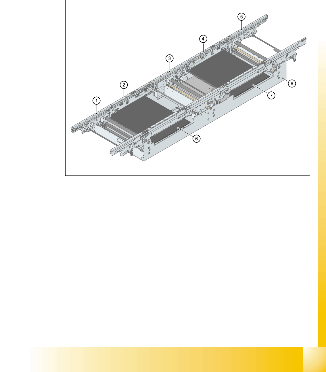
9.1.9 Structure of the single conveyor
On the HF’s and the HS-60, the single conveyor consists of the input conveyor, two placement
areas, the intermediate conveyor and the output conveyor. The conveyor has an automatic width
adjustment unit and a lifting table for clamping the PCB.
Fig. 9.1 - 1 PCB transport - single conveyor (HF)
Key
(1) Input conveyor (2) Placement area 1
(3) Intermediate conveyor (4) Placement area 2
(5) Output conveyor (6) Lifting table placement area 1
(7) Lifting table placement area 2 (8) Mounting frame