SG_FSE_SiplaceHF_HF3_00193901-05_eng.pdf - 第516页
1 - 42 S tudent Guide SIPLACE HF/HF3 1 1 MTC 2 Edition 09/2005 42 2a. T ransfer position of the T ower 1 XL WTC 11 When you press the button to calibrate the T ransf er positio n the tray move s approx. 5mm outside of th…
1 - 41
Student Guide SIPLACE HF/HF3
Edition 09/2005 11 MTC 2
41
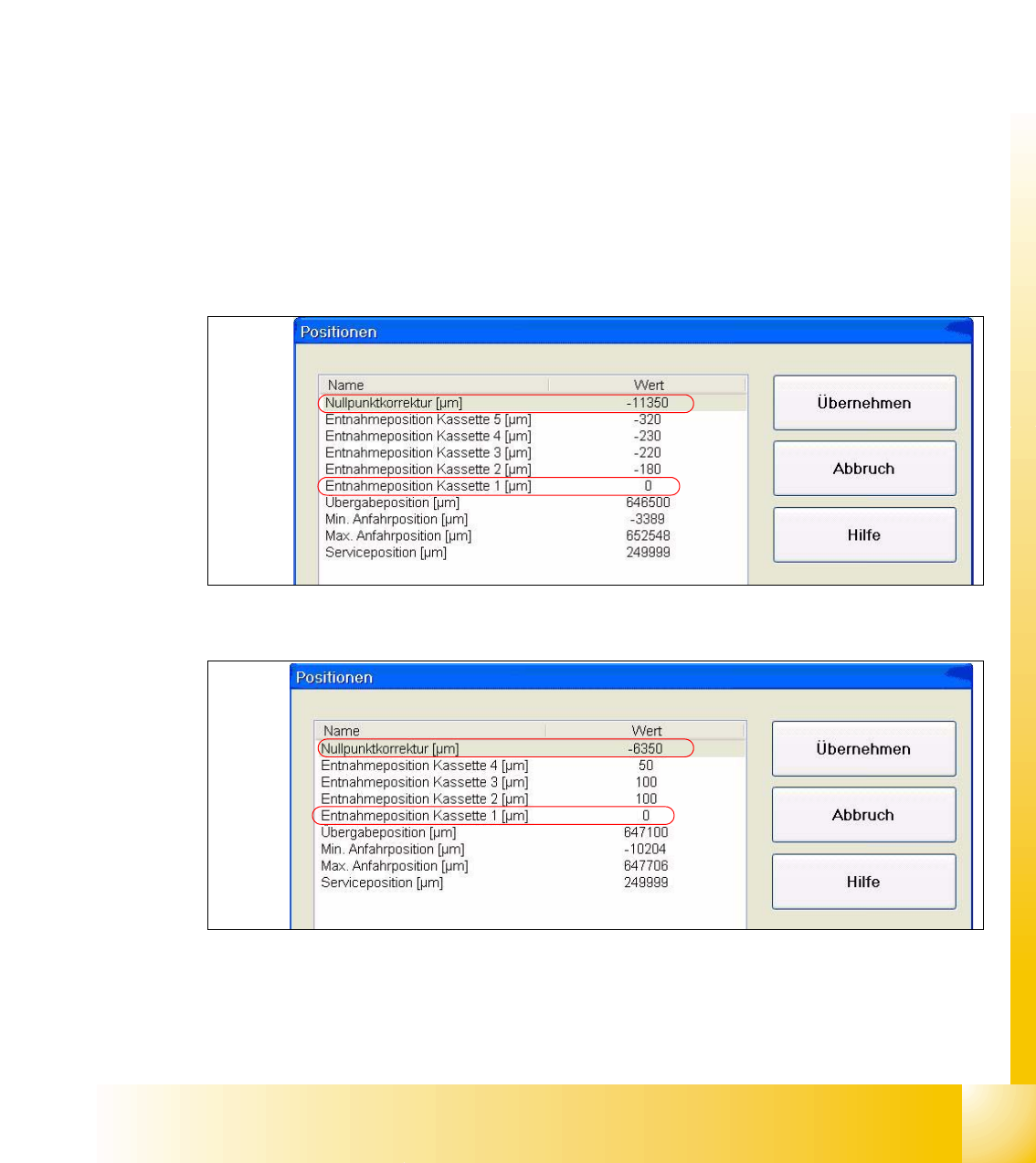
1b. Manuall Input of the Zero point correction 11
After the calibration of the zeropoint correction , the value will put in the row " removal position
Cassette 1" from the machine data.
Is this value to big, it is not possible to calibrate the max. and min. travel range of the feed axis.
Reason: The travel range will be calculate from the row "Zero point correction". When you have
the value zero in the row zero point correction, the feed axis move against the limit switch during
the calibration procedure.
Solution:
Put in the calibrated value in the row "Zero point correction" and the value zero in the row " Position
of removal Position cassette 1".
Sitest:
–MTC -->Axes
– Choose feed axis
– Press the button "Positions"
Fig. 11.3 - 6 Example: Input machine data tower 1
Fig. 11.3 - 7 Example: Input machine data tower 2
After the manuall Inputs, check the Zero point correction again.
1 - 42
Student Guide SIPLACE HF/HF3
11 MTC 2 Edition 09/2005
42
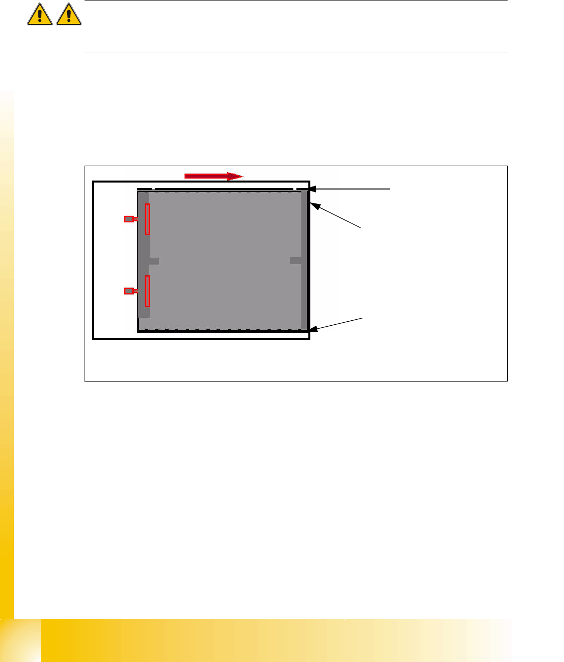
2a. Transfer position of the Tower 1 XL WTC 11
When you press the button to calibrate the Transfer position the tray moves approx. 5mm outside
of the feed axis.
Attention:
When you accept this calibration procedure with "ACCEPT" now, you get a wrong transfer position
and pick up position for the twin head.
➠ Open the cover and move the tray back in the direction to the lifting axes
➠ Then move the tray back in the direction to the machine and stop so that the plastic edge
comes into line with outer edge of the frame from the feed axis. You must do this in one step,
because that you eliminate the tolerance between the space and the driver and you don‘t need
a pick up offset for the tray.
Fig. 11.3 - 8 Transfer position XL tray
Plastic edge of the WTC
Edge of the frame from the MTC
Plastic edge of the WTC
1 - 43
Student Guide SIPLACE HF/HF3
Edition 09/2005 11 MTC 2
43
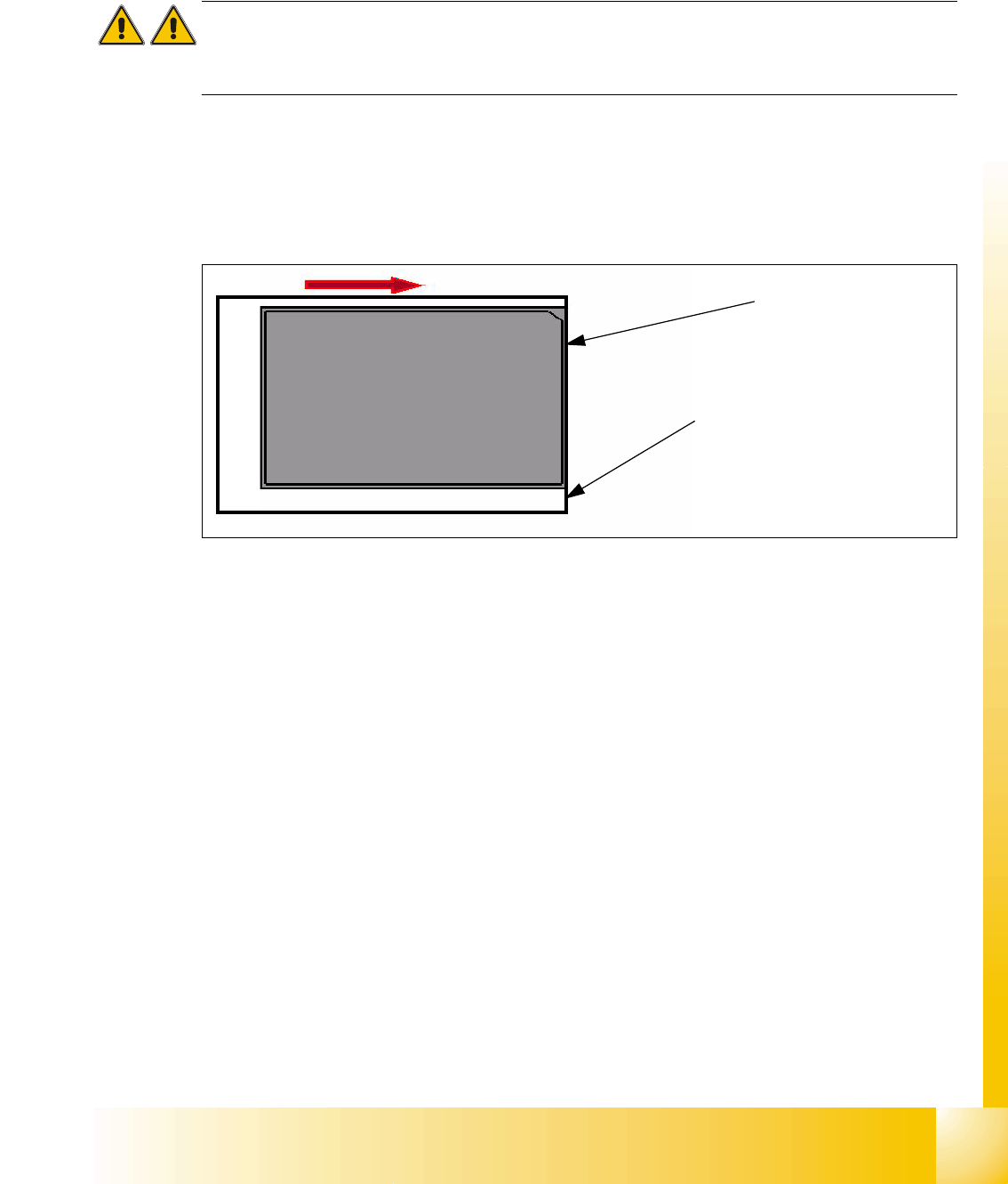
2b. Transfer position of the Tower 2 WTC 11
When you press the button to calibrate the Transfer position the tray moves out and stops approx.
5mm before the feed axis end.
Attention:
When you accept this calibration procedure with "ACCEPT" now, you get a wrong transfer position
and pick up position for the twin head.
➠ Then move the tray in the direction to the machine and stop so that the plastic edge comes into
line with outer edge of the frame from the feed axis. You must do this in one step, because that
you eliminate the tolerance between the space and the driver and you don‘t need a pick up
offset for the tray.
Fig. 11.3 - 9 Transfer position JEDEC tray
During the production the trays move a different way to her pick up position but the Y Position of
the machinen (pick up postion) of both trays is the same.
Plastic edge of the WTC
Edge of the frame from the MTC