SG_FSE_SiplaceHF_HF3_00193901-05_eng.pdf - 第223页
1 - 23 S tudent Guide SIPLACE HF/HF3 Edition 09/2005 6 Colle ct &Place-Head / DLM2 23 6.3 Placement sequence Pick up and Placement Cycle of the Collect & Place head (DLM2) 6 6.3.1 Working positions at the placeme…
1 - 22
Student Guide SIPLACE HF/HF3
6 Collect &Place-Head / DLM2 Edition 09/2005
22
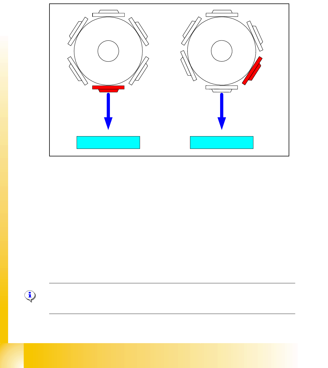
6.2.10 Height reference run
With this function we check the correct fitting on the sleeve and the correct nozzle type which is
programmed.
The nozzle length is taken to calculate the pick up and placement height for the following place-
ments.
Fig. 6.2 - 10 Measure nozzle height
1. Top of the fixed conveyor rail
2. First step with segment 1 for measure the nozzle height.
3. Last step with segment 6 (12) for measure the nozzle height.
– The gantry moves the placement heads above the fixed conveyor rail.
– The Z- axis runs down, and all nozzles touch the transport rail.
– Nozzle 1 defines the reference length.
– All segments are measured according to there specific length reffering to nozzle 1.
– The maximum length tolerance is 0,4 mm: If the length difference is too high an error message
is displayed.
Please Note
Exception: special nozzle with type number X9X are only measured (there is no length specifica-
tion).
4
1
5
2
3
6
4
1
5
2
3
6
1
23
1 - 23
Student Guide SIPLACE HF/HF3
Edition 09/2005 6 Collect &Place-Head / DLM2
23
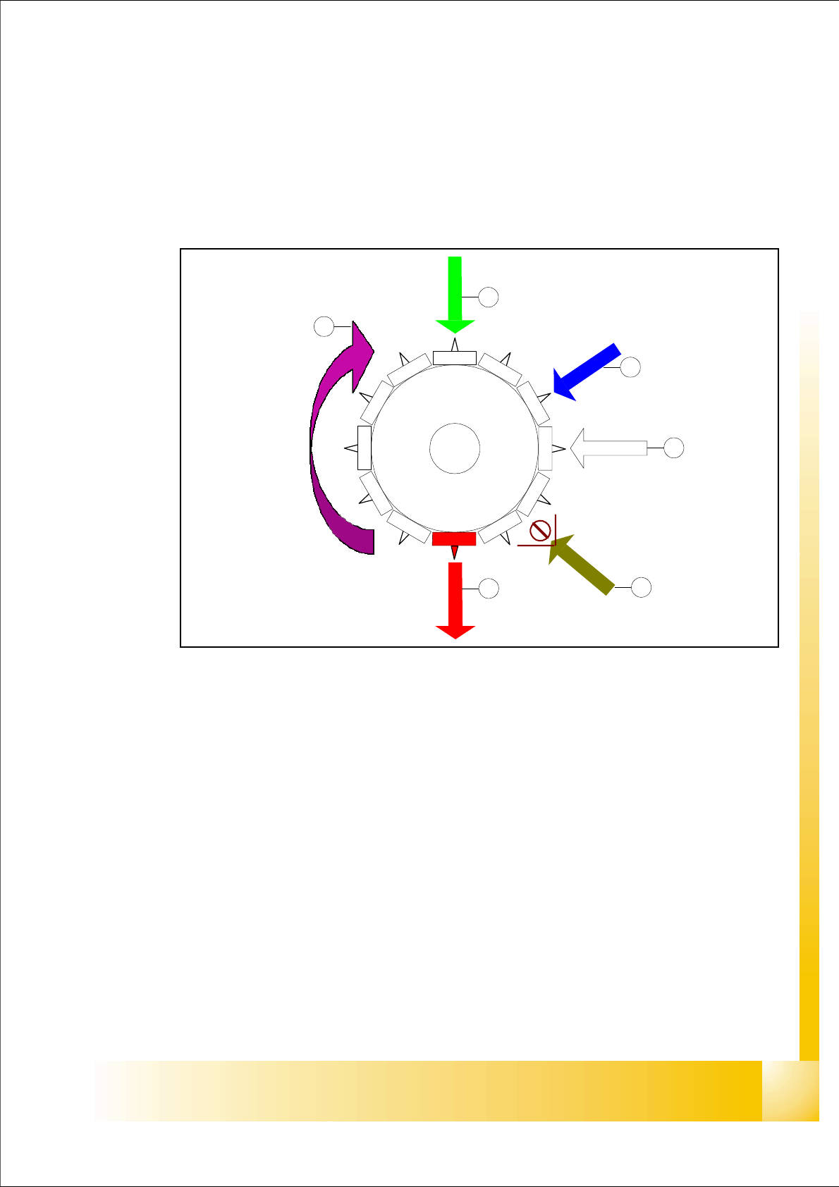
6.3 Placement sequence
Pick up and Placement Cycle of the Collect & Place head (DLM2) 6
6.3.1 Working positions at the placement head
Fig. 6.3 - 1 Working positions at the placement head
Key
(1) Optical centering
(2) turning station
(3) service position for segment; Removal of the sleeve on the opposite side
(4) pick up / placement / reject position
(5) working direction
(6) option: component sensor
12
1
1
1
0
9
8
7
6
5
1
2
3
4
1
2
3
4
5
6
1 - 24
Student Guide SIPLACE HF/HF3
6 Collect &Place-Head / DLM2 Edition 09/2005
24
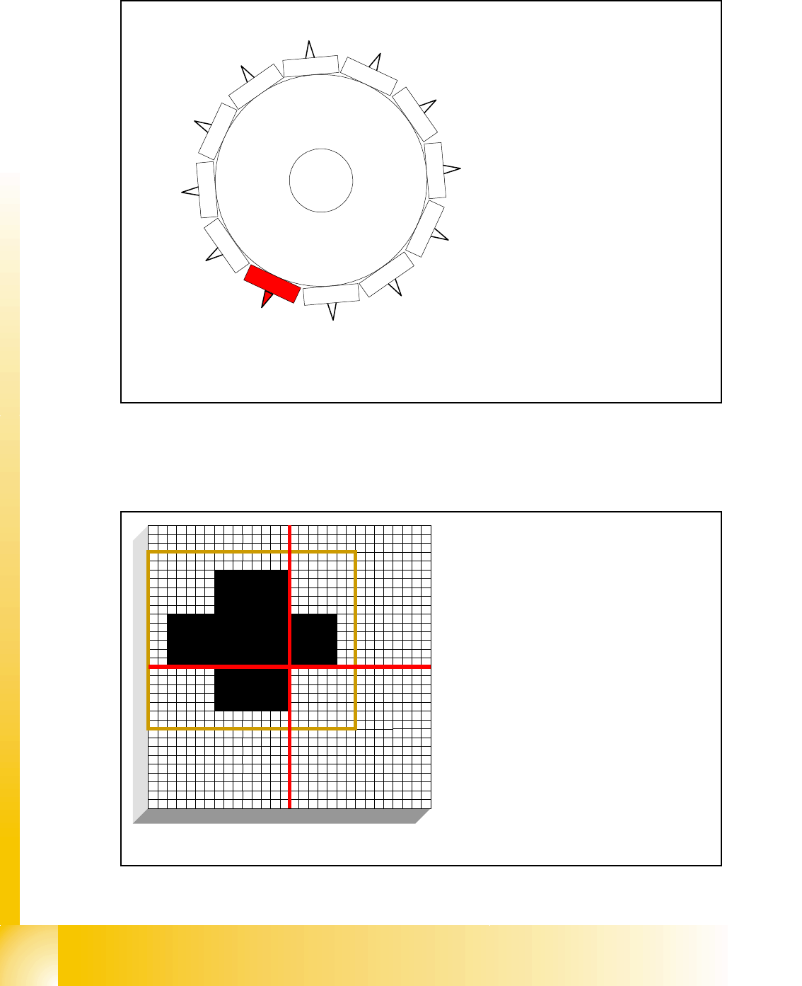
6.3.2 12 nozzle Collect & Place head in home position 15
°
Fig. 6.3 - 2 12 nozzle Collect & Place head in home position
6.3.3 PCB position recognition run to the PCB nominal position
Fig. 6.3 - 3 PCB position recognition run to the PCB nominal position
1
2
1
1
1
0
9
8
7
6
5
1
2
3
4
the Star-axis is turned to home position.
When the X- and Y-axis is in waiting position
Star position:
15 degrees
Digit: 15.000
1 degree is equivalent to 1000 digits
The fiducial is expected at this nominal posi-
tion. The PCB camera is moved from waiting
position to this fiducial position.
– PCB position recognition is done before
the first component is picked up.
– The gantry axes move the PCB camera to
the theoretical fiducial position. The cam-
era takes the picture of the first fiducial
and the vision system calculates the cen-
ter position.