SG_FSE_SiplaceHF_HF3_00193901-05_eng.pdf - 第378页
1 - 10 S tudent Guide SIPLACE HF/HF3 8 Component handling Edition 09/2005 10 8.2.4 Optionally extension on the COT 8.2.4.1 T ape reel holder for the 3th reel at the 3x8mm S-Feeder When using 3x 8mm S-Feeder it wou ld be …
1 - 9
Student Guide SIPLACE HF/HF3
Edition 09/2005 8 Component handling
9
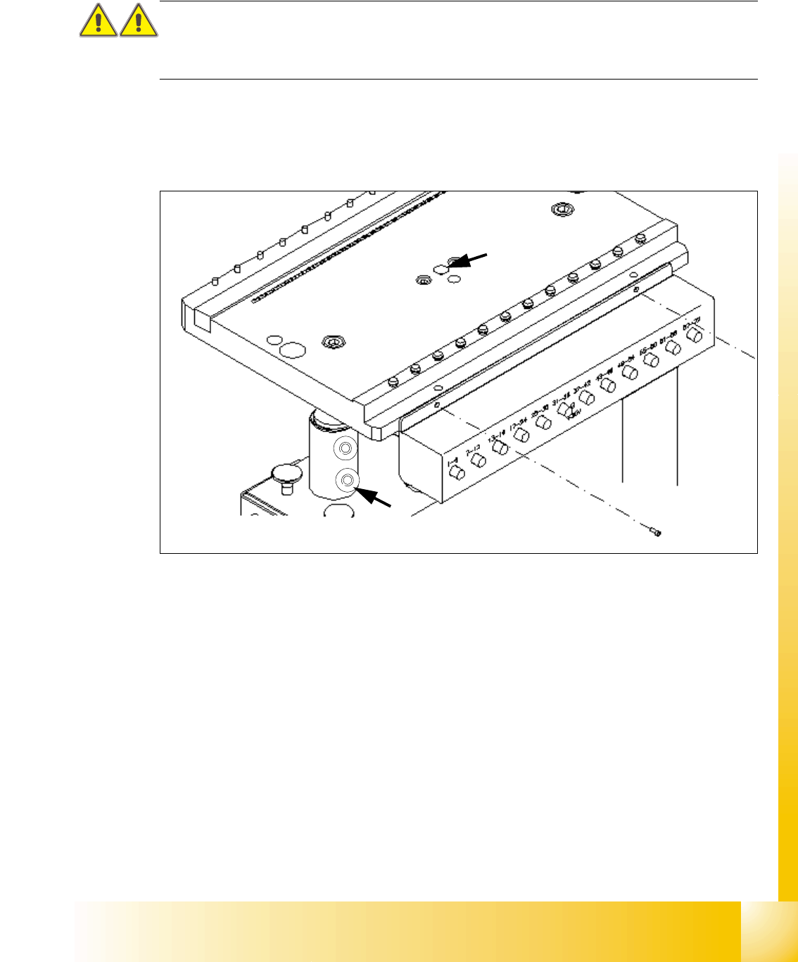
8.2.3 Adjustment the COT height
This task requires 2 more persons to increase and decrease the COT height.
CAUTION:
Use always the eye-bolt to fix the component plate, independend if you increase or reduce the
component table height, otherwise you may hurt your fingers.
➠ Attach the hooks of the lifting device to the eye-bolt (2) and fix the lifting plate.
➠ (at model 1) losen the 4 fixing scrwews on each of the 2 COT frame sides.
➠ (Model 2) Remove the 2 cotter pins from the sleeve shaft.
Fig. 8.2 - 6 Adjusting the COT height
Legend
Increasing and reducing the COT height 8
➠ Raise the component table top part until to rich the desired position of the height from the com-
ponent table.
➠ Put back the 2 cotter pins into the drilling hole of the sleeve shaft.
respective fix the fixing screws on each COT frame side.
➠ Unscrew the eye-bolt from the component trolley bed.
➠ Now, COT height is adjusted.
(1)Drilling hole for eye-bolt 2. Hole for the cotter pins
1
2
1 - 10
Student Guide SIPLACE HF/HF3
8 Component handling Edition 09/2005
10
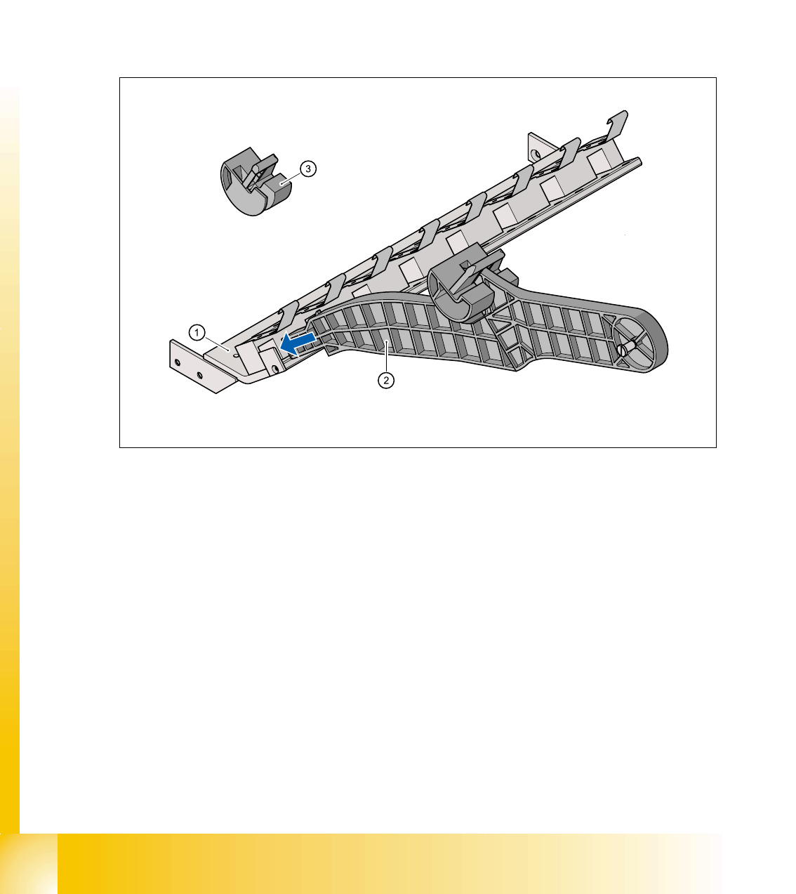
8.2.4 Optionally extension on the COT
8.2.4.1 Tape reel holder for the 3th reel at the 3x8mm S-Feeder
When using 3x8mm S-Feeder it would be necessary to install the tape reel holder for the3th pick
up track on the COT. The option allows unwinding of the tape easily and decrease machine
stoppage.
The adapter plate (Pos. 1) is fixed inside the COT with four screws. The adapter plate for the tape
reel holder will be mounted under the communication unit. In this mechanical device hang up the
holder for the 3th tape reel.
Fig. 8.2 - 7 Tape reel holder on the COT(left) / Mechanical device for the tape reel holder (right)
Legend
(1)Adapter plate 2. Tape reel holder
3. Idler pulley, shortened
1 - 11
Student Guide SIPLACE HF/HF3
Edition 09/2005 8 Component handling
11
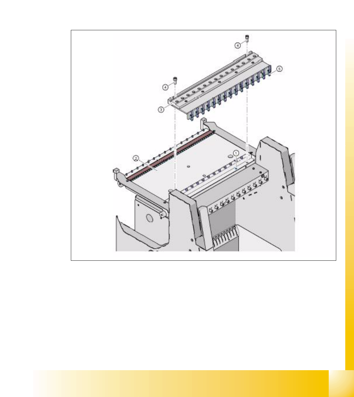
8.2.4.2 Compressed air supply for Bulkcase feeder
Bulkcase feeder need for operation pressure air supply. So this pressure air supply is offered as
an option .
it is easy to mount. First remove the bung (Pos. 1) at pressure air hose in the feeder table (Pos.
2). Than the pneumatic supply for the bulck case feeder is mounted (Pos. 3) with 2 screws DIN
912, M8x20 (Pos. 4) on the component table (Pos. 2). At the rear side of the airkiss supply unit
are feeder clamps mounted (Pos. 5). This clamps keep the Bulkcase-feeder down correctly sealed
to the pressure air supply.
Fig. 8.2 - 8 Unit for bulkcase feeder
Legend
(1)Bung at component table 2. Componnent table
3. Pressure air supply for Bulkcase-Feeder 4. Screw DIN 912, M8x20
5. clamps for bulkcase feeder