SG_FSE_SiplaceHF_HF3_00193901-05_eng.pdf - 第276页
1 - 76 S tudent Guide SIPLACE HF/HF3 6 Collect &Place-He ad / DLM2 Edition 09/2005 76 6.5.2 Nozzle changer for 6 segment C&P head The nozzle changer for a 6 se gment C&P head consists of at least one, an d up…
1 - 75
Student Guide SIPLACE HF/HF3
Edition 09/2005 6 Collect &Place-Head / DLM2
75
6.5 Nozzle changer
The Siplace HF/HF3 is supplied with 6 segment or 12 segment collect&place heads. As an option,
a nozzle changer can be installed for each collect&place head. This enables the nozzle configu-
ration to be changed quickly, thus allowing the Collect&Place head to be quickly adapted to the
needs of the placement process.
6.5.1 Nozzle changer for 12 segment C&P head
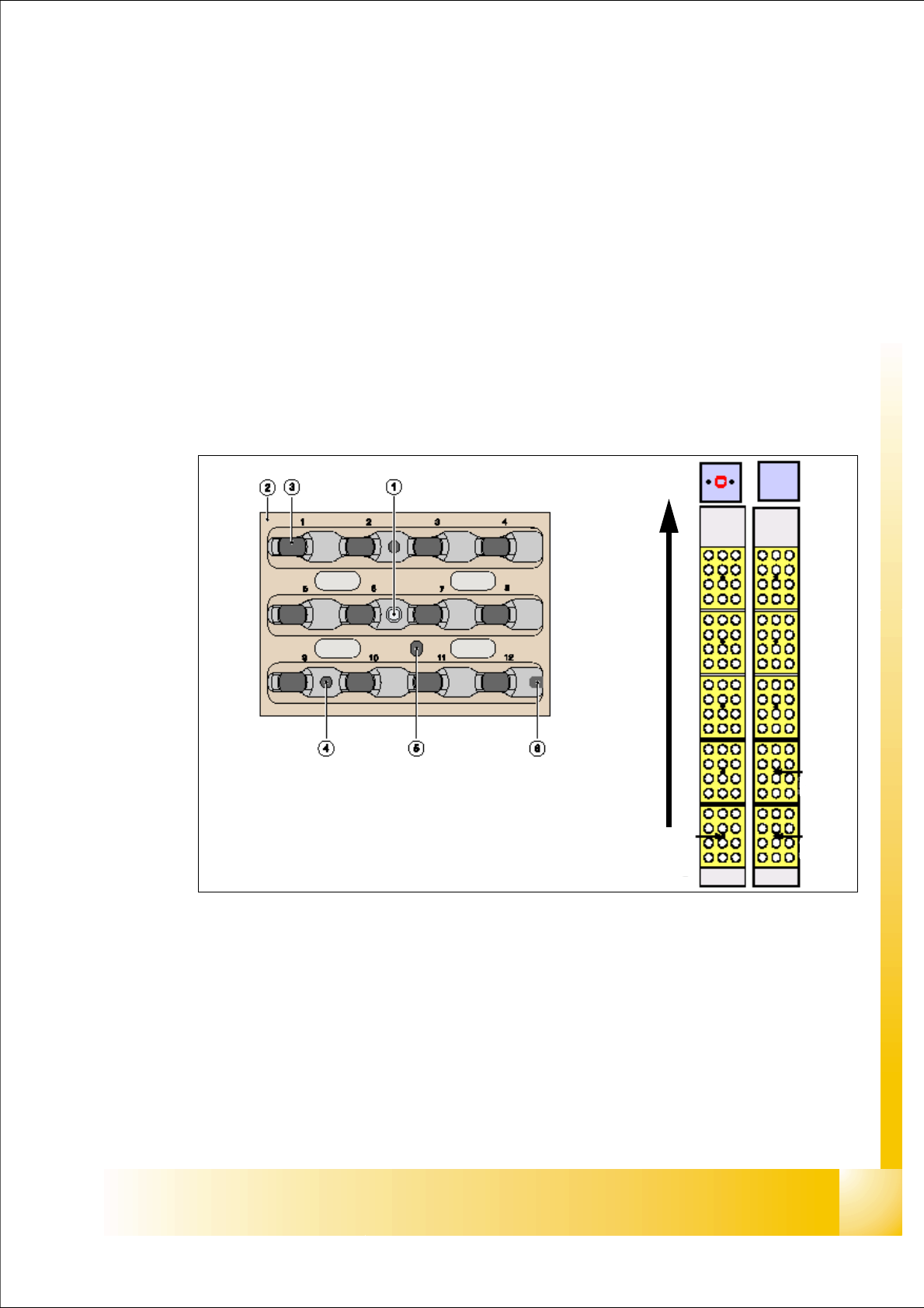
The nozzle changer consists of at least one, and up to ten magazines, each with twelve nozzle
garages (see Fig. 6.5 - 1). The magazines are seated on a common support and each magazine
is centered using two parallel pins and fixed in place with a spring hook.
Fig. 6.5 - 1 Nozzle changer and Nozzle Magazin 12 segment C&P head
Legend
(1) Magazine position fiducial (2) Nozzle garage
(3) Locking Plate (4) Hole for the parallel pin for centering the
magazine
(5) Hole for the parallel pin to slide locking
mechanism
(6) Slot for the parallel pin for centering the
magazine
Magazin 6
Magazin 2
Magazin 1
Transport direction
1 - 76
Student Guide SIPLACE HF/HF3
6 Collect &Place-Head / DLM2 Edition 09/2005
76
6.5.2 Nozzle changer for 6 segment C&P head
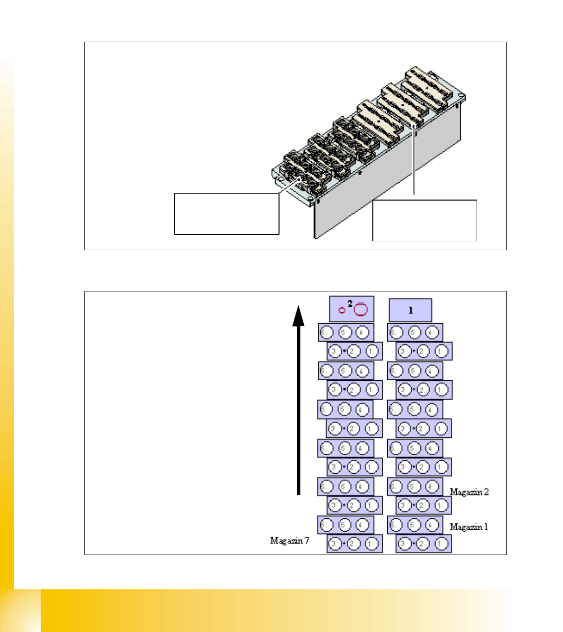
The nozzle changer for a 6 segment C&P head consists of at least one, and up to twelve maga-
zines, each with six nozzle garages (see Fig. 6.5 - 2). The magazines are seated on a common
support and each magazine is centered using two parallel pins and fixed in place with a spring
hook.
Magazines for the 9xx and 8xx nozzle types can be set up. The magazine types can be arranged
as required.
Fig. 6.5 - 2 Nozzle changer 6 segment C&P head
Fig. 6.5 - 3 Description of the positions nozzle changer
Magazin for 6
nozzle Typ 8xx
Magazin for 6
nozzle Typ 9xx
Transport direction
(1) Component reject position
(2) Nozzle reject position
1 - 77
Student Guide SIPLACE HF/HF3
Edition 09/2005 6 Collect &Place-Head / DLM2
77
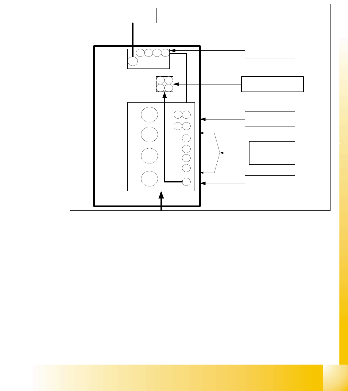
6.5.3 Control nozzle changer on the C&P heads
The nozzle changer are controlled via CAN Bus. Depending on the location at the machine the
SLIO at Main- or Sub-Distributor is used. At HF-machine version ’A’ the nozzle changer is control-
led via the "One Wire Bus". Solenoid valves activate the pneumatic rotary drives to open or close
the nozzle changer.
Fig. 6.5 - 4 Pressure air supply for the nozzle changer
3
4
2
1
Gantry 1 - 4
4
3
2
1
Bulkcase
Feeder
COT 1-4
2,5 bar
adjustable
Nozzle
changer
1 2
34
Nozzle changer
Gantry 1 - 4
2,5 bar
adjustable
Docking unit
1 - 4
5 bar
adjustable
Conveyor
5 bar
adjustable
5 bar
adjustable
1 2 3 4
Tape cutter
1 - 4
4 3
21