SG_FSE_SiplaceHF_HF3_00193901-05_eng.pdf - 第296页
1 - 96 S tudent Guide SIPLACE HF/HF3 6 Collect &Place-He ad / DLM2 Edition 09/2005 96 6.7.2 Head Modularity at HF3 machine For the HF machine, we have the following possibilities: Gantry 1 – 12-Segment Collect&Pl…
1 - 95
Student Guide SIPLACE HF/HF3
Edition 09/2005 6 Collect &Place-Head / DLM2
95
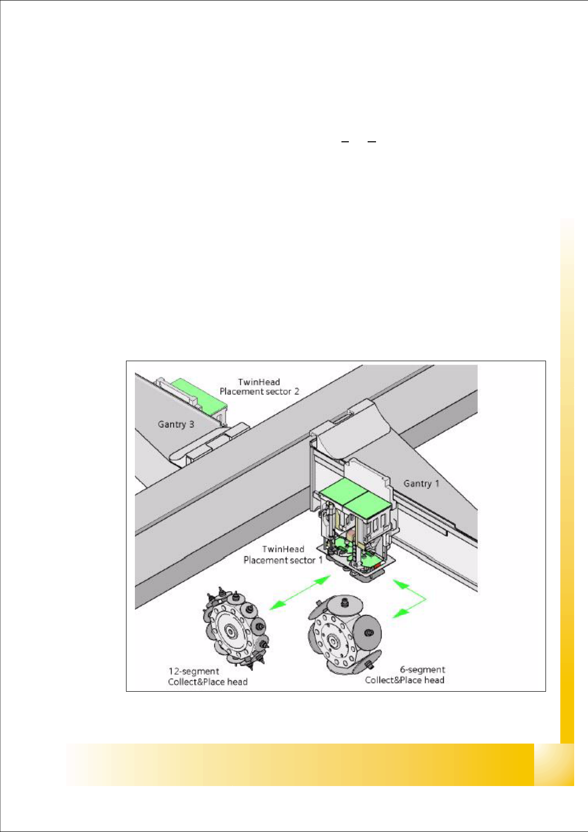
6.7 Head Modularity
6.7.1 Head Modularity at HF machine
A very useful feature in the SIPLACE family is its Head Modularity HM. For the HF machine, we
have the following possibilities:
Gantry 1
– 12-Segment Collect&Place-head or
– 6-Segment Collect&Place-head or
– SIPLACE TWIN-head)
Gantry 3
– SIPLACE TWIN-head (504)
– 12-Segment Collect&Place-head (505) or
– 6-Segment Collect&Place-head (505)
A simple handling to change the head, the machine can be fit to the current production require-
ments.
Fig. 6.7 - 1 Head modularity HF
1 - 96
Student Guide SIPLACE HF/HF3
6 Collect &Place-Head / DLM2 Edition 09/2005
96
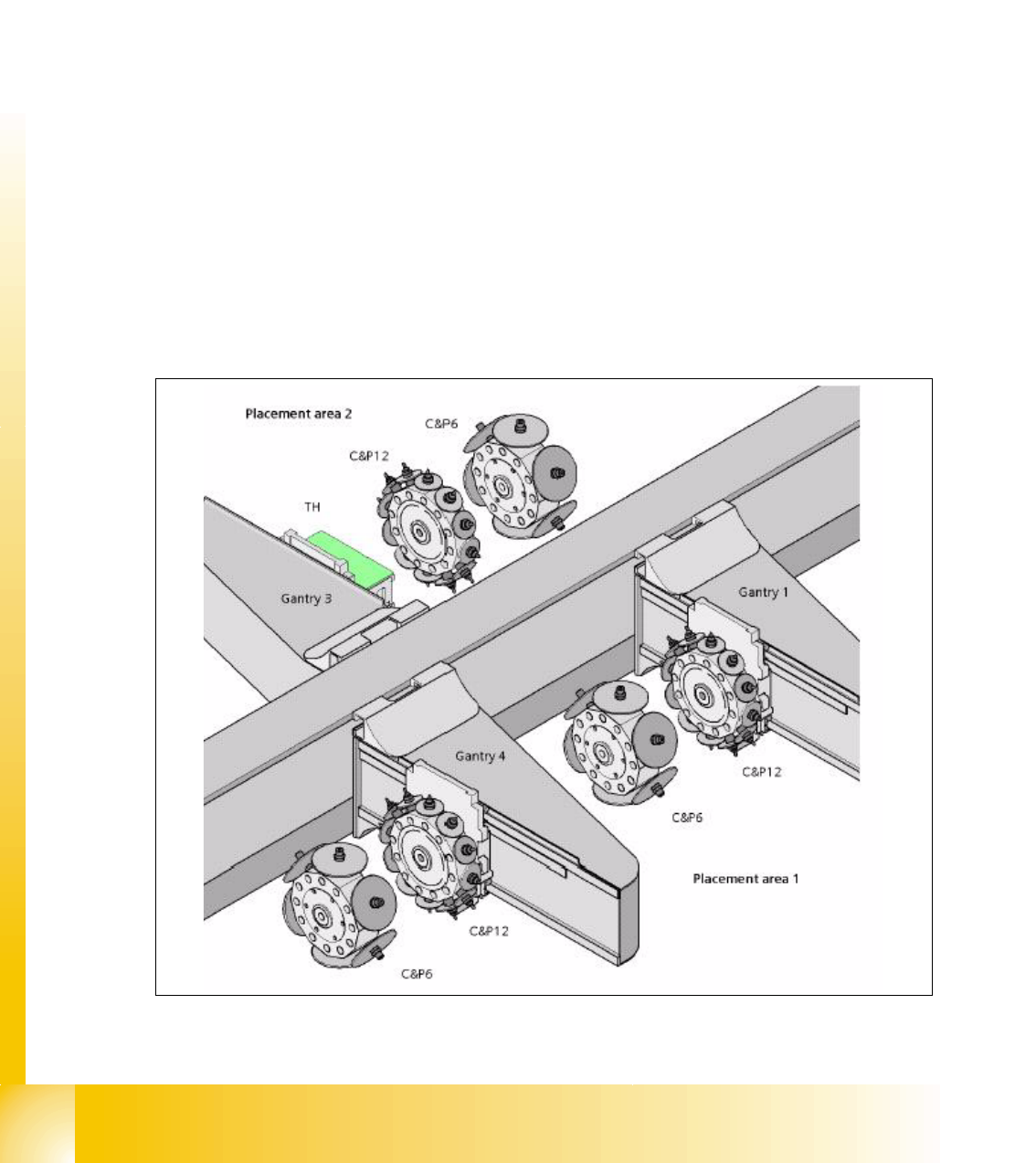
6.7.2 Head Modularity at HF3 machine
For the HF machine, we have the following possibilities:
Gantry 1
– 12-Segment Collect&Place-head or
– 6-Segment Collect&Place-head
Gantry 3
– 12-Segment Collect&Place-head or
– 6-Segment Collect&Place-head or
– SIPLACE TWIN-Head)
Gantry 4
– 12-Segment Collect&Place-head or
– 6-Segment Collect&Place-head
A simple handling to change the head, the machine can be fit to the current production require-
ments.
Fig. 6.7 - 2 Head modularity HF3
1 - 97
Student Guide SIPLACE HF/HF3
Edition 09/2005 6 Collect &Place-Head / DLM2
97
6.7.3 Production requirements
Please Note:
The reconfiguration of the Siplace HF should exist for a longer production time of a product and
not occur by the week because the configuration and the calibration of the machine uses appro-
ximately one day. 6
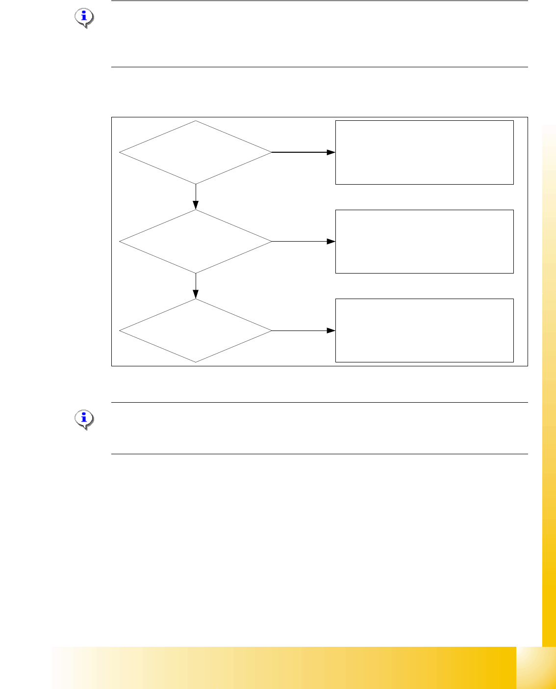
Which decisions must be taken before head exchange?
Fig. 6.7 - 3 Means of deciding between C&P head and Twin head
Please Note:
In the case of a PCB with different component sizes, you should decide for which C&P head install
her (12 segment C&P head or 6 segment C&P head). 6
Only IC`s respective Odd
shape placement?
Mixed fast IC`s respective
Odd shape placement?
Only fast chip`s and IC`s
placement?
HF: Gantry 1 / 3 -->Twin head
HF3:Gantry 1 / 4 -->6 Segment C&P head
Gantry 3 -->Twin head
(On HF3, Twin head only on Gantry 3)
HF: Gantry 1 --> 12 Segment C&P head
Gantry 3 --> Twin head
HF3:Gantry 1/4 --> 12 Segment C&P head
Gantry 3 --> 6 Segment C&P head
HF: Gantry 1 -->C&P head
Gantry 3 -->Twin head
HF3:Gantry 1 -->12 Segment C&P head
Gantry 4 -->6 Segment C&P head
Gantry 3 -->Twin head
Yes
Yes
Yes