SG_FSE_SiplaceHF_HF3_00193901-05_eng.pdf - 第569页
1 - 6 S tudent Guide SIPLACE HF/HF3 14 T est Equipm ent Edition 09/2005 6 m Four BNC socket s, impedance 50 Ohm The sockets can be assign ed as required with the following signals: – Track signal A or B TTL level, max. 5…
1 - 5
Student Guide SIPLACE HF/HF3
Edition 09/2005 14 Test Equipment
5
l Dynamic function display for the membrane key assignments on the LCD display
m Five membrane keys for menu control
n Green operating display LED
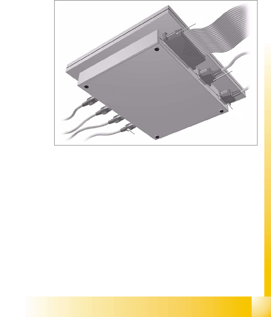
fig.: 14.2 - 2 Axis tester – bottom view
j Connection for ribbon cable
Connection on the axis tester: 37-pin sub-D connector
Connection on the axis controller:
– 37-pin sub-D connector for S-20/23/25/F4/F5 and HS-50 machines with A361 or A362 axis
controllers
– 25-pin sub-D connector for S-15/F3, G and wafflepack changer machines with A360 axis
controllers
An adapter is attached to the ribbon cable in order to connect the 25-pin axis controller.
The axis controller supplies the
+ 5 VDC ± 5 % and
± 15 VDC ± 5 %
operating voltages to the axis tester via the 37-pin ribbon cable.
k 9-pin sub-D connector for the CAN bus cable, e.g. for connecting CAN bus-controlled boards
in the placement machine (transmission speed 128 kBaud to 1 Mbaud, impedance 120 Ohm).
l 9-pin sub-D connector for the serial interface cable (V24), e.g. for connecting an external PC
(max. transmission speed 188 kBaud).
j
k
l
m

1 - 6
Student Guide SIPLACE HF/HF3
14 Test Equipment Edition 09/2005
6
m Four BNC sockets, impedance 50 Ohm
The sockets can be assigned as required with the following signals:
– Track signal A or B TTL level, max. 5 V
– Zero pulse TTL level t
min
= 1 ìsec
– End signal TTL level t
min
> 10 msec
– Trigger TTL level t
min
> 10 msec
– Counting error TTL level, trigger signal from counting error sensor for the
oscilloscope
–V
setpoint
± 10 V, analog signal, R
i
= 10 kOhm
– Force ± 10 V analog signal, R
i
= 10 kOhm
–V
REG
(total current) ± 10 V analog signal, R
i
= 10 kOhm
– Position deviation ± 10 V analog signal; the signal is generated internally in the axis
tester.
14.2.1 Package
The complete SIPLACE axis tester, part no. 03002801-01, is supplied with the following compo-
nents:
– SIPLACE Axis Tester, part no. 03000761-01
– Test cable A361 ... A363 (length 150 cm), with 37-pin plug and 37-pin socket for connecting to
the axis controllers of S2x, F4/F5 and HS placement machines,
part no. 03002803-01
– CAN bus cable, part no. 00349679-03
– RS232 C cable, part no. 03002804-01
– Manual for axis tester, part no. 00193370-01
1 - 7
Student Guide SIPLACE HF/HF3
Edition 09/2005 14 Test Equipment
7
14.3 Axis Test Box (former version) and Adapter Board
Item no: Axis test box, including adapter board 00303430-06 14
Item no: Axis test box 00328041-05 14
Item no: Cable 00304771-03 14
Item no: Adapter board 00328040-01 14
Applica-
tion:
14
The axis test box is used in connection with the test adapter axis, for calibration of the dynamics
of the axes. (Placement head axes and gantry axes).
14
14
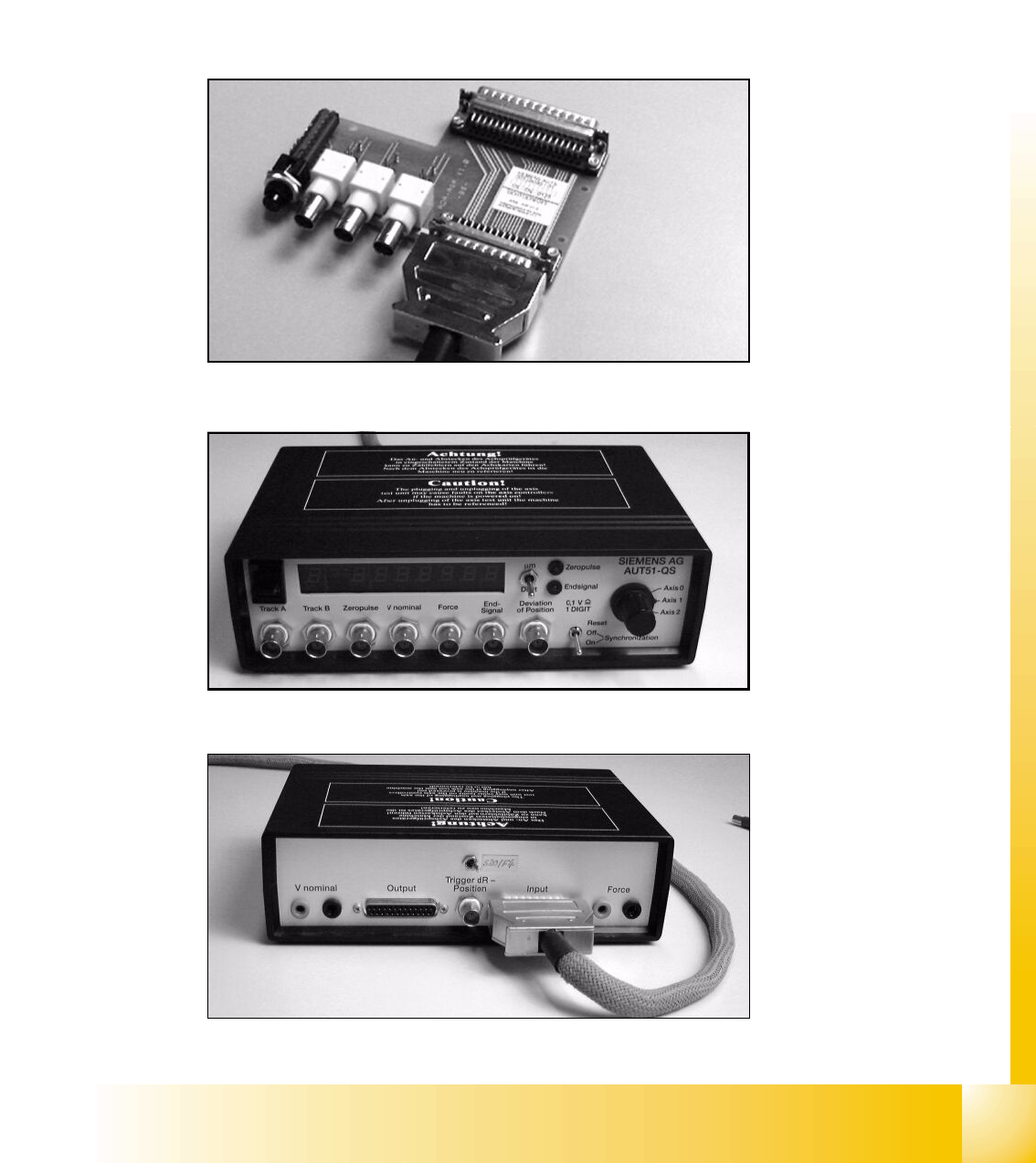
fig. 14.3.1 Adapter board for axis test box, item no: 00328040-01
14
fig.: 14.3 - 2 SIPLACE axis test box, front view
14
fig.: 14.3 - 3 SIPLACE axis test box, back view