SG_FSE_SiplaceHF_HF3_00193901-05_eng.pdf - 第420页
1 - 34 S tudent Guide SIPLACE HF/HF3 9 Modular convey or Edition 09/2005 34 9.3 Conveyor control 9.3.1 TSP 301 transport control for HF Fig. 9.3 - 1 Jumper setting for TSP 301 conveyor control J1 / J2 J1 / J2 Siem ens SM…
1 - 33
Student Guide SIPLACE HF/HF3
Edition 09/2005 9 Modular conveyor
33
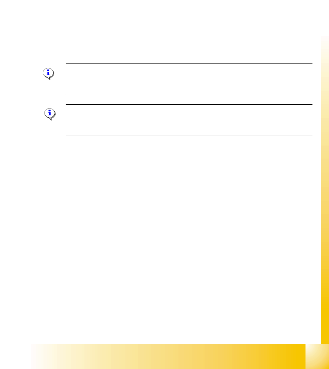
9.2.12 Checks after mechanical work on the conveyor
1. Check: Distance between the top edge of the conveyor belt and the top stop.
This value should be
6 mm .
2. Check: Distance between the top edge of the conveyor belt and the top stop, at the clamping
sensor.
This value should be
5.8 mm.
3. Check: Distance between clamping actuator (lifting table) and top edge of the belt.
This value should be
94.2 mm on the HF and HS-60.
4. Check: Distance between clamping actuator (lifting table) and top edge of belt at the clamping
sensor.
This value should be
94.4 mm on the HF and HS-60.
Note for machine with clamping sensor:
The actuator must be seated 0.2 - 0.3 mm deeper below the clamping sensor to ensure that the
piezo sensor (force sensor) is triggered reliably.
Please Note: for machine without clamping sensor:
The distance between clamping actuator (lifting table) and top edge of the belt should be on all
four positions 94,0mm.
1 - 34
Student Guide SIPLACE HF/HF3
9 Modular conveyor Edition 09/2005
34
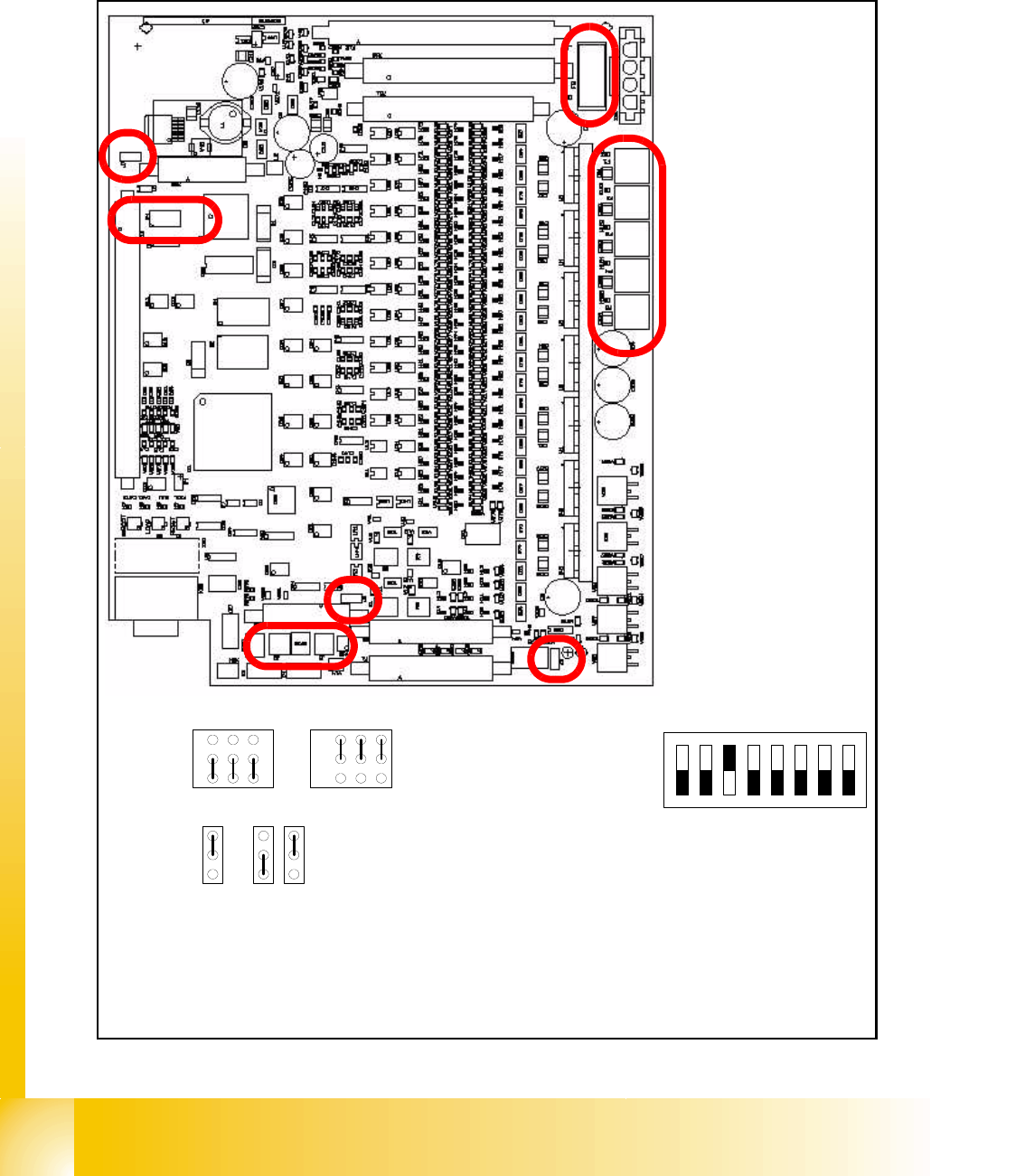
9.3 Conveyor control
9.3.1 TSP 301 transport control for HF
Fig. 9.3 - 1 Jumper setting for TSP 301 conveyor control
J1 / J2J1 / J2
Siemens SMEMA
1
2
3
J3 J6 J7
3
2
1
3
2
1
OFF
78
ON
123456
DIL Switch S4
J1 Previous station
J2 Next station
J3 Interference loop
J6 CAN bus 1 Terminator (not used)
J7 CAN bus 2 Terminator
S4 DIL switch:
1-OFF = Siplace HS-60
2-OFF = Not used
3-ON = Clamping sensor active
*
3-OFF = Clamping sensor deactivated
4-8 OFF = Not used
* depend on the machine equipment
J3
J2
J1
S4
J7
J6
F6 Main Fuse TSP301
F1 - F5 Fuses for the
conveyor motors
1 - 35
Student Guide SIPLACE HF/HF3
Edition 09/2005 9 Modular conveyor
35
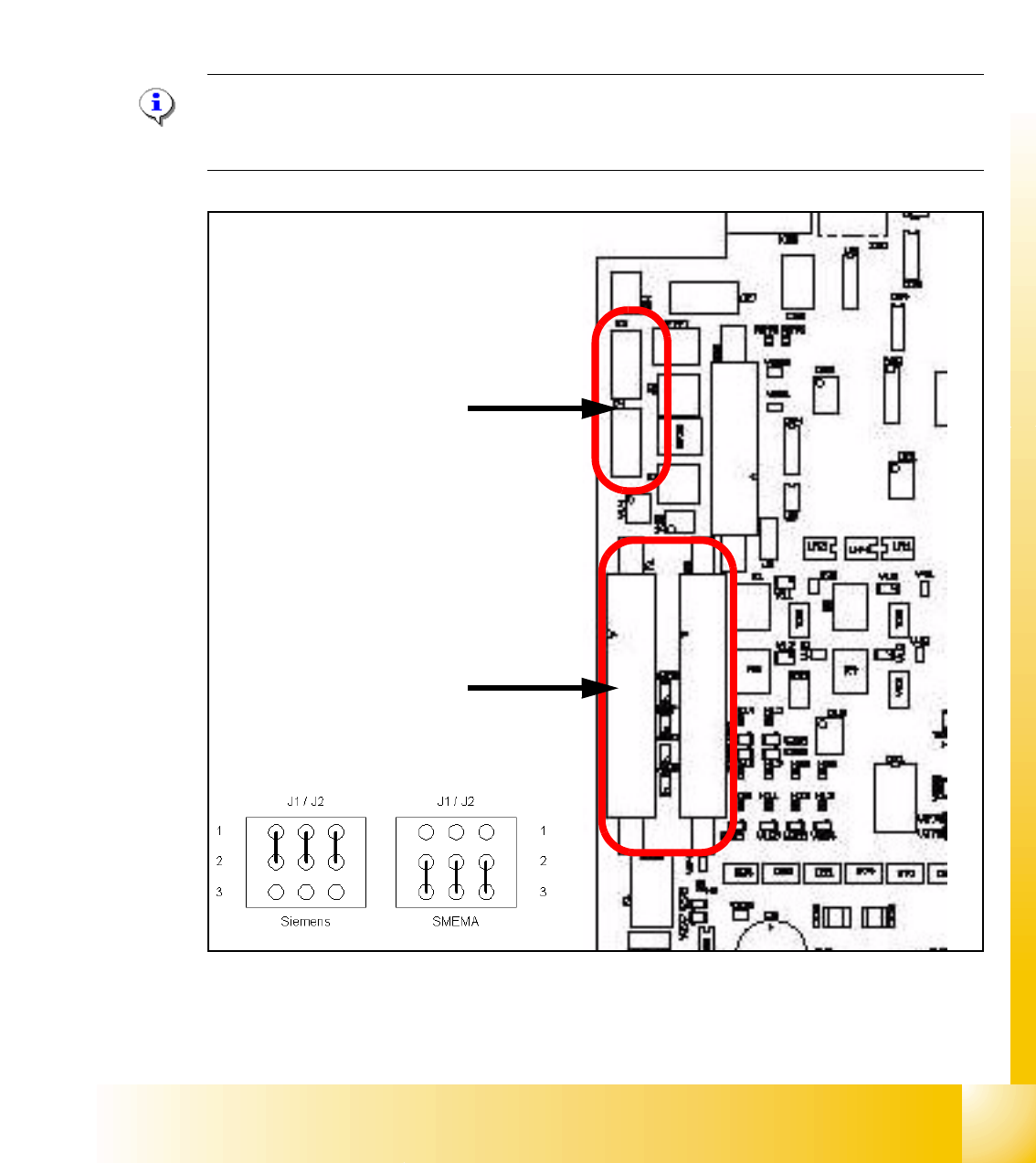
9.3.2 Transport control board TSP 301 with Siemens interface(Option)
Following modification are necessary for using the Siemens interface:
(1) Application: no modification.
(2) JumperJ1 / J2: have to change (see below).
(3) Disconnect the connector X3 and X4 on the TSP 301!
(4) Connect the Siemens interface cable on the connector X1 and X2.
Please Note:
The 10 pin Locking-Clip connector of the SMEMA-connector have to disconnected from the
TSP301! Destruction of the TSP board!
Fig. 9.3 - 2 TSP 301 SMEMA --> Siemens
➠ 10 pin connector for SMEMA- Interface
X3 Previous Station
X4 Next Station
➠ Connector for Siemens-Interface
X1 Previous Station
X2 Next Station