SG_FSE_SiplaceHF_HF3_00193901-05_eng.pdf - 第116页
1 - 2 S tudent Guide SIPLACE HF/HF3 Contents Edition 09/2005 2 4.3.3.6 Safety valve X60 . . . . . . . . . . . . . . . . . . . . . . . . . . . . . . . . . . . . . . . . . . . . . . . . . 42 4.3.3.7 Pneumatic loop Cooling …

Student Guide SIPLACE HF/HF3
Edition 09/2005 Contents
1
Chapter
Table of Contents
4 Services to the machine. . . . . . . . . . . . . . . . . . . . . . . . . . . . . . . . . . . . . . . . . . . . . . 3
4.1 Overview. . . . . . . . . . . . . . . . . . . . . . . . . . . . . . . . . . . . . . . . . . . . . . . . . . . . . . . . . . . . . . . . . . . . . . . 3
4.1.1 Overview power supply . . . . . . . . . . . . . . . . . . . . . . . . . . . . . . . . . . . . . . . . . . . . . . . . 4
4.2 Power Supply on HF . . . . . . . . . . . . . . . . . . . . . . . . . . . . . . . . . . . . . . . . . . . . . . . . . . . . . . . . . . . . . 7
4.2.1 Naming Convention of Connectors and Cables . . . . . . . . . . . . . . . . . . . . . . . . . . . . . 7
4.2.2 Main distribution Unit, section 2. . . . . . . . . . . . . . . . . . . . . . . . . . . . . . . . . . . . . . . . . . 8
4.2.3 Sub distribution Unit, section 4 . . . . . . . . . . . . . . . . . . . . . . . . . . . . . . . . . . . . . . . . . . 9
4.2.4 Power Supply Unit. . . . . . . . . . . . . . . . . . . . . . . . . . . . . . . . . . . . . . . . . . . . . . . . . . . 10
4.2.4.1 Input Voltage . . . . . . . . . . . . . . . . . . . . . . . . . . . . . . . . . . . . . . . . . . . . . . . . . . . 13
4.2.4.2 Transformer 1. . . . . . . . . . . . . . . . . . . . . . . . . . . . . . . . . . . . . . . . . . . . . . . . . . . 14
4.2.4.3 Transformer 2. . . . . . . . . . . . . . . . . . . . . . . . . . . . . . . . . . . . . . . . . . . . . . . . . . . 15
4.2.4.4 Voltages in the Power Supply Unit after switching on . . . . . . . . . . . . . . . . . . . . 16
4.2.4.5 DC/DC Converter in Main Power Supply . . . . . . . . . . . . . . . . . . . . . . . . . . . . . . 17
4.2.5 Power Supply Computer Unit . . . . . . . . . . . . . . . . . . . . . . . . . . . . . . . . . . . . . . . . . . 18
4.2.6 Power Supply Axis Unit. . . . . . . . . . . . . . . . . . . . . . . . . . . . . . . . . . . . . . . . . . . . . . . 19
4.2.7 DC/DC Converter Vision section 2 . . . . . . . . . . . . . . . . . . . . . . . . . . . . . . . . . . . . . . 20
4.2.7.1 Power Supply Tape Cutter . . . . . . . . . . . . . . . . . . . . . . . . . . . . . . . . . . . . . . . . . 20
4.2.8 Safety and Control Loop(HF/HF3 bis MA.Nr. xx) . . . . . . . . . . . . . . . . . . . . . . . . . . . 21
4.2.8.1 Émergency Stop Loop (safety loop). . . . . . . . . . . . . . . . . . . . . . . . . . . . . . . . . . 21
4.2.8.2 Control loop . . . . . . . . . . . . . . . . . . . . . . . . . . . . . . . . . . . . . . . . . . . . . . . . . . . . 22
4.2.8.3 How does the emergency stop loop work?. . . . . . . . . . . . . . . . . . . . . . . . . . . . . 24
4.2.9 The Safety Combination (K6 Relay) . . . . . . . . . . . . . . . . . . . . . . . . . . . . . . . . . . . . . 25
4.2.9.1 How does the SSK latch?. . . . . . . . . . . . . . . . . . . . . . . . . . . . . . . . . . . . . . . . . . 27
4.2.10 Various Signal . . . . . . . . . . . . . . . . . . . . . . . . . . . . . . . . . . . . . . . . . . . . . . . . . . . . . 27
4.2.10.1 Software Release (Software Enabled) . . . . . . . . . . . . . . . . . . . . . . . . . . . . . . . 27
4.2.10.2 Security Loop OK signal. . . . . . . . . . . . . . . . . . . . . . . . . . . . . . . . . . . . . . . . . . 28
4.2.10.3 Control On signal . . . . . . . . . . . . . . . . . . . . . . . . . . . . . . . . . . . . . . . . . . . . . . . 29
4.2.11 Power Distribution . . . . . . . . . . . . . . . . . . . . . . . . . . . . . . . . . . . . . . . . . . . . . . . . . . 30
4.3 Pneumatic System. . . . . . . . . . . . . . . . . . . . . . . . . . . . . . . . . . . . . . . . . . . . . . . . . . . . . . . . . . . . . . 33
4.3.1 In General . . . . . . . . . . . . . . . . . . . . . . . . . . . . . . . . . . . . . . . . . . . . . . . . . . . . . . . . . 33
4.3.2 HF Pneumatic System. . . . . . . . . . . . . . . . . . . . . . . . . . . . . . . . . . . . . . . . . . . . . . . . 34
4.3.3 Pneumatic unit. . . . . . . . . . . . . . . . . . . . . . . . . . . . . . . . . . . . . . . . . . . . . . . . . . . . . . 35
4.3.3.1 Manometer Arrangement . . . . . . . . . . . . . . . . . . . . . . . . . . . . . . . . . . . . . . . . . . 36
4.3.3.2 Compressed air distribution in Main Pneumatic Unit . . . . . . . . . . . . . . . . . . . . . 37
4.3.3.3 Switch on Sequency Pneumatic Units . . . . . . . . . . . . . . . . . . . . . . . . . . . . . . . . 39
4.3.3.4 Main Valve , main regulator X59 for machine components . . . . . . . . . . . . . . . . 40
4.3.3.5 Proportional valve, proportional regulator X58. . . . . . . . . . . . . . . . . . . . . . . . . . 41

1 - 2
Student Guide SIPLACE HF/HF3
Contents Edition 09/2005
2
4.3.3.6 Safety valve X60. . . . . . . . . . . . . . . . . . . . . . . . . . . . . . . . . . . . . . . . . . . . . . . . . 42
4.3.3.7 Pneumatic loop Cooling Y - Linear motor for Placement area 1/2 . . . . . . . . . . . 43
4.3.3.8 Pneumatic loop Cooling X - Linear motor for Placement area 1. . . . . . . . . . . . . 44
4.3.4 Pneumatic Supply Tape Cutter . . . . . . . . . . . . . . . . . . . . . . . . . . . . . . . . . . . . . . . . . 44
4.3.5 Pneumatic Supply Docking Unit (Compnent-table 1-4). . . . . . . . . . . . . . . . . . . . . . . 45
4.3.6 Bulk Case System and Nozzle Changer . . . . . . . . . . . . . . . . . . . . . . . . . . . . . . . . . . 45
4.3.7 Pneumatic Supply Collect and Place Haed . . . . . . . . . . . . . . . . . . . . . . . . . . . . . . . . 46
4.3.8 Pneumatic Supply Twin Head:. . . . . . . . . . . . . . . . . . . . . . . . . . . . . . . . . . . . . . . . . . 47
4.3.8.1 Air distribution TWIN-head . . . . . . . . . . . . . . . . . . . . . . . . . . . . . . . . . . . . . . . . . 48
4.3.8.2 Z-axis safety process . . . . . . . . . . . . . . . . . . . . . . . . . . . . . . . . . . . . . . . . . . . . . 50
1 - 3
Student Guide SIPLACE HF/HF3
Edition 09/2005 4 Services to the machine
3
4 Services to the machine
4.1 Overview
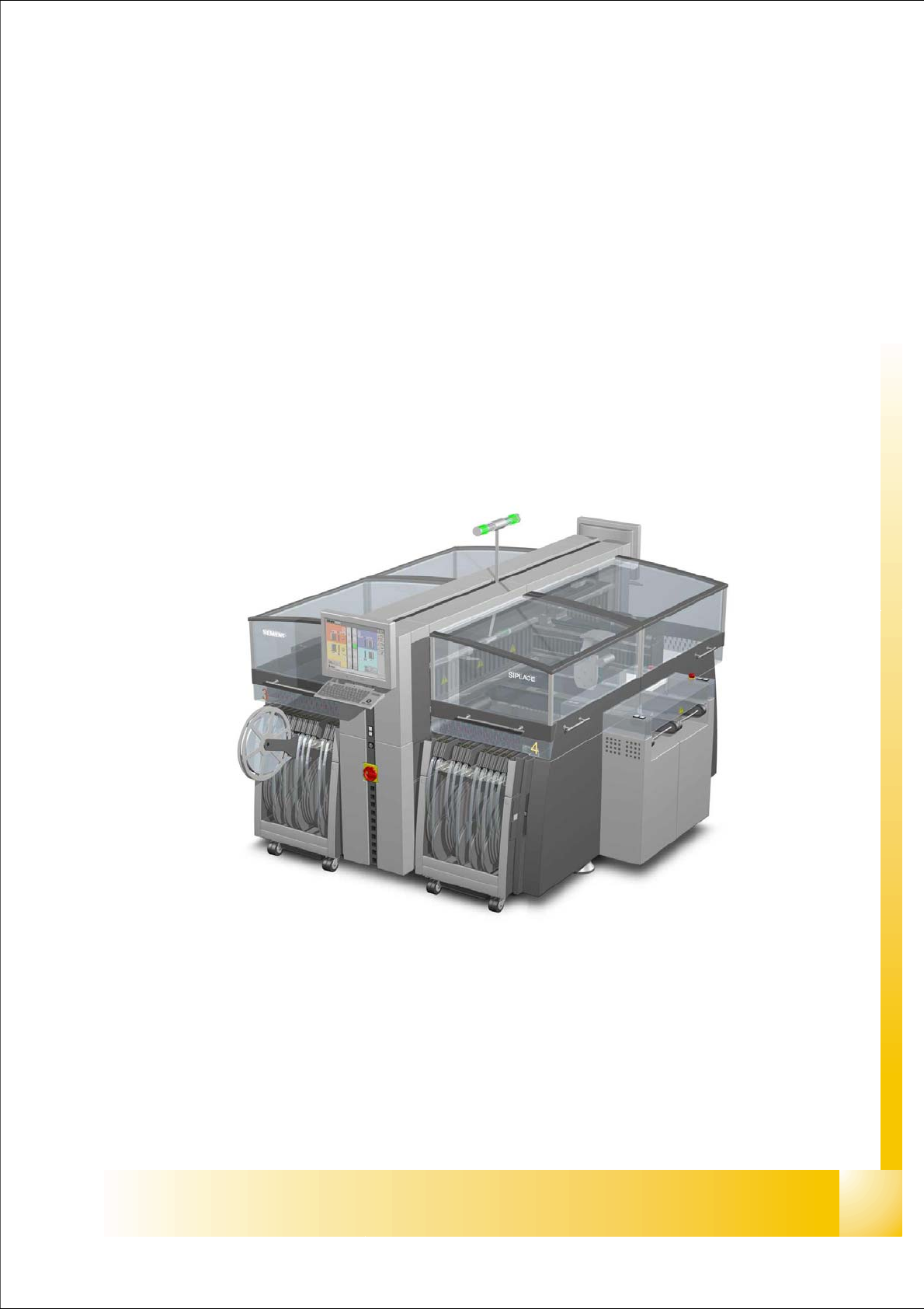
the figure below shows the position of the units which create and distribute the supply voltages
needed to operate the system
– power supply unit containing main distributor (pos. 1)
– section distributor section 2 (pos. 2)
– pneumatic unit (pos. 3)
– section distributor section 4 (pos. 4)
Fig. 4.1 - 1 HF/HF3 main units identical at original - and ’A’ version of HF-machine
P
o
w
e
r
s
u
p
p
l
y
Section 4
Section 2
P
n
eu
m
at
ic
U
n
it
3
1
4
2