SG_FSE_SiplaceHF_HF3_00193901-05_eng.pdf - 第37页
1 - 1 1 S tudent Guide SIPLACE HF/HF3 Edition 09/2005 2 Overview 11 2.2.2.1 Overview V olt ages on the front p anel of the power supply unit Fig. 2.2 - 4 Frontside Power supply K1 K2 / K3 / K4 K6 K5 F1/F14 F2 / F10 / F6 …
1 - 10
Student Guide SIPLACE HF/HF3
2 Overview Edition 09/2005
10
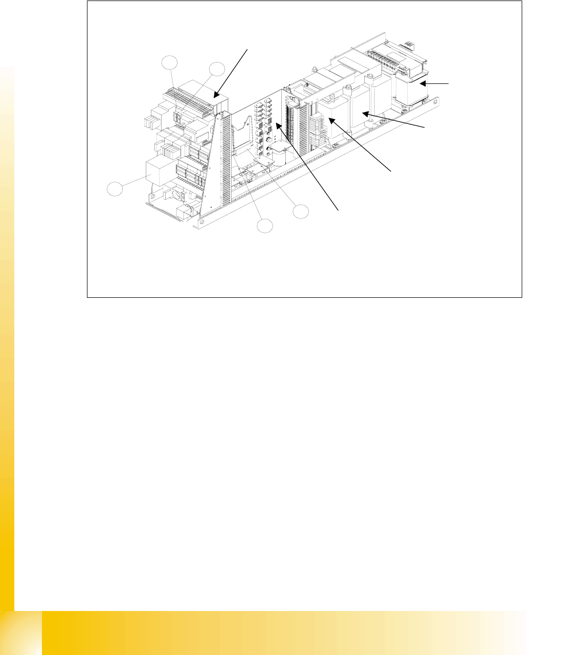
2.2.2 Power supply unit
The main power supply unit is mounted on a compact slide-in module, and located on the left side
of the middle section. When viewed from the outside only the red main power switch is visible.
A lockable door prevents access to the unit.
Fig. 2.2 - 3 Power supply
Legend
(1) DC / DC Converter 24 V (2) DC / DC Converter 5 V and 5V/24V for HF3
(3) Safety combination relais K6 (4) F5 fuse for Star axis
(5) F11for Inrush current limiter transformer
1
2
3
4
5
main distributor main
power supply
Inrush current limiter:
a: transformer: EST
b: servo: Ess
transformer T2
transformer T1
T1
T2
Fuse F61 - fuse F142
1 - 11
Student Guide SIPLACE HF/HF3
Edition 09/2005 2 Overview
11
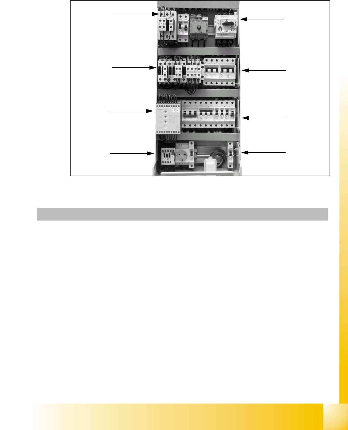
2.2.2.1 Overview Voltages on the front panel of the power supply unit
Fig. 2.2 - 4 Frontside Power supply
K1
K2 / K3 / K4
K6
K5
F1/F14
F2 / F10 / F6 / F8 /
F12 / F13
F4 / F7
F11 / F5
Q1 / Q2
Units Identification Contact Voltages
X100 connecting terminal panel
Power supply
L1, L2, L3 3 x 204 VAC / 3 x 380 VAC
3 x 400 VAC / 3 x 415 VAC
X102 Service socket 115 VAC / 220 VAC / 230 VAC / 240
VAC
Q1 Main switch 1, 3, 5 u.
2, 4, 6
3 x 204 VAC / 3 x 380 VAC
3 x 400 VAC / 3 x 415 VAC
Q2 Motor protective switch 1, 3, 5 u.
2, 4, 6
3 x 204 VAC / 3 x 380 VAC
3 x 400 VAC / 3 x 415 VAC
K1 main contactor 1, 3, 5 u.
2, 4, 6
3 x 204 VAC / 3 x 380 VAC
3 x 400 VAC / 3 x 415 VAC
K2 contactor 1, 3, 5 u.
2, 4, 6
3 x 177 VAC
K3 contactor 1, 3, 5 u.
2, 4, 6
3 x 177 VAC
K4 contactor 1, 3, 5 u.
2, 4, 6
3 x 177 VAC

1 - 12
Student Guide SIPLACE HF/HF3
2 Overview Edition 09/2005
12
K5 contactor A1 (+) – A2
(-)
1,2
3,4
5,6
24VDC
24 VDC
against ground
24 VDC against ground
24 VDC against ground
K6 (SSK)
protective contactor
combination
L+, X3, X5 24 VDC against ground
F1 Fuse Service socket;
1-pol.
1, 2 115 VAC / 220 VAC
230 VAC / 240 VAC
F2 Fuse Component table;
3-pol.
1, 3, 5 u.
2, 4, 6
3 x 36 VAC
F4 Fuse X- / Y-Axis;
3-pol.
1, 3, 5 u.
2, 4, 6
3 x 177 VAC
F5 Fuse Star-Axis;
1-pol.
1, 2 145 VDC
against ground
F6 Fuse Z- and DP-Axis;
1-pol.
1, 2 39 VDC against ground
F7 Fuse supply system on
bord;
3-pol.
1, 3, 5 u.
2, 4, 6
3 x 230 VAC
F8 Fuse PCB Conveyor;
1-pol.
1, 2 33 VDC
against ground
F10 Fuse rectifier V7 and V70;
3-pol.
1, 3, 5 u.
2, 4, 6
3 x 39 VAC
F11 Fuse inrush limiter; 1-pol. 1, 2 33,6 VDC
against ground
F12 Fuse illumination
1-pol.
1, 2 52 VDC against ground
F13 Fuse Monitor;
1-pol.
1, 2 26 VDC against ground
F14 Fuse Blower Y-Motor;
1-pol.
1, 2 26 VDC against ground
F61 / F62 Fuse rectifier V4 3 x 28 VAC
F81 / F82 Fuse rectifier V5 3 x 23,8 VAC
F111 / F112 Fuse rectifier V8 3 x 23,8 VAC
F131 / F132 Fuse rectifier V10 3 x 19,7 VAC
F141 / F142 Fuse rectifier V11 3 x 18,7 VAC