SG_FSE_SiplaceHF_HF3_00193901-05_eng.pdf - 第266页
1 - 66 S tudent Guide SIPLACE HF/HF3 6 Collect &Place-He ad / DLM2 Edition 09/2005 66 6.4.7 Adjusting the Stop for the Z-Axis 6.4.7.1 T ools and Equipment – Set of DIN 91 1 Allen keys – Gauge for Z-limit stop, item n…
1 - 65
Student Guide SIPLACE HF/HF3
Edition 09/2005 6 Collect &Place-Head / DLM2
65
6.4.6 Belt tension Z-axis
Please Note:
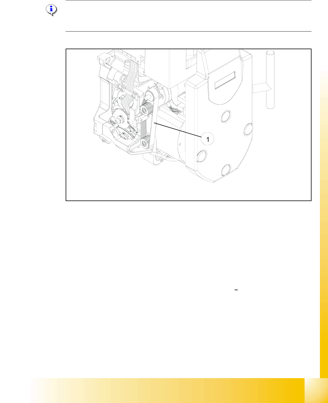
The measuring point of the measuring pin must be in the middle of the two deflection pulleys.
The measuring pin should be at a maximum distance of 2 - 3 mm, from the toothed belt. 6
Fig. 6.4 - 13 Measuring point for the belt tension of the Z-axis
Legend Fig. 6.4 - 13
(1) Measurement point for the belt tension
➠ Attach the measuring head in front of the toothed belt (1) .
➠ Strike the toothed belt, to reach a stimulation of vibration of the open ended toothed belt.
➠ Stretch the belt over the fastening of the driving motor (compare: service manual) if the
frequency of the belt tension does not reach a value of
280 Hz + 10 Hz.
➠ Repeat these instructions until the belt tension is correct.
1 - 66
Student Guide SIPLACE HF/HF3
6 Collect &Place-Head / DLM2 Edition 09/2005
66
6.4.7 Adjusting the Stop for the Z-Axis
6.4.7.1 Tools and Equipment
– Set of DIN 911 Allen keys
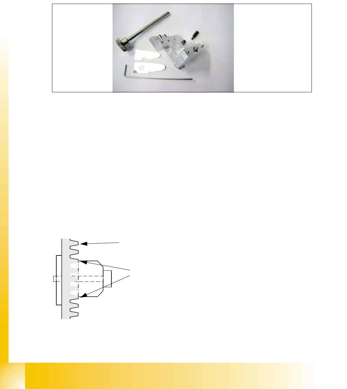
– Gauge for Z-limit stop, item no.03019865-01
Fig. 6.4 - 14 Gauge for Z-limit stop
6.4.7.2 General
With the softwareversion 503.02 and higher the calculation of the zero point correction of the
Z-axis is done with the star in a position of 2700 digits. During the reference run the Z axis (star
axis position +2700 digits) now moves down and up into the aperture. To ensure that the Z axis is
located correctly in the center of the raceway/aperture, it must be possible for the Z axis to move
into the aperture up to the limit stop. This is only possible if the Z limit stop is set correctly.
Preconditions: 6
Before you start with the setting please check the followings:
– Belt tension Z-Axis
– Correctly mounted clamping device on the Z-axis belt.
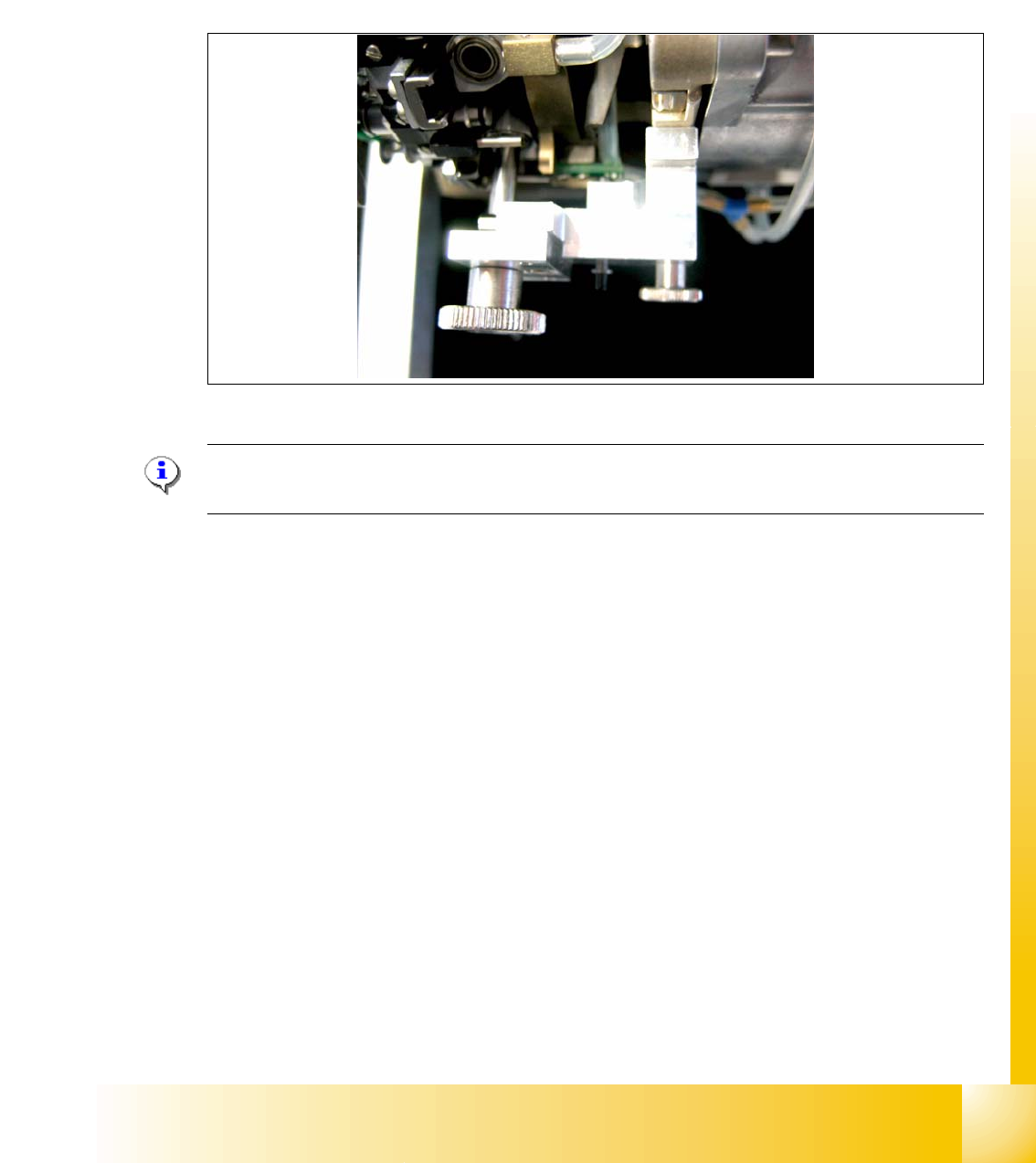
Fig. 6.4 - 15 Clamping device Z-axis
You ensure, so that the clamping device is firmly fixed between the teeth of the drive belt.
Tooth on the drivebelt
Clamping device between the
teeth of the drive belt
1 - 67
Student Guide SIPLACE HF/HF3
Edition 09/2005 6 Collect &Place-Head / DLM2
67
6.4.7.3 Settings
➠ Switch off the machine. The setting can, however, be made directly on the machine.
➠ The star gauge for setting the Z limit stop is mounted on the C&P head in exactly the same way
as the zero point gauge for the star.
➠ Remove the segment 1 from the star and turn the star, so that the gauge pin is inserted on
segment 1.
Fig. 6.4 - 16 Z-Limit stop gauge mounted
Please Note:
For DLM 1 heads an additional adapter must be mounted for the gauge.
– The star gauge ensures that the star is at the correct position and the Z axis is pushed up-
wards.
➠ To obtain better access to the Z limit stop, you should unscrew the cable clip on one side and
twist it away. Push the ribbon cable carefully aside.
➠ Use the 5/100 mm feeler gauge to check that it can be moved freely (without resistance) bet-
ween the Z limit stop and the clamp. (Fig. 6.4 - 17)
If this is not the case, the limit stop must be adjusted.